Continue to Site

Welcome to EDAboard.com

Welcome to our site! EDAboard.com is an international Electronics Discussion Forum focused on EDA software, circuits, schematics, books, theory, papers, asic, pld, 8051, DSP, Network, RF, Analog Design, PCB, Service Manuals... and a whole lot more! To participate you need to register. Registration is free. Click here to register now.

24V interface to micro

Status
Not open for further replies.

Booleano

Junior Member level 1
Joined
Jun 9, 2009
Messages
19
Helped
0
Reputation
0
Reaction score
0
Trophy points
1,281
Activity points
1,401
Hi all,

I need to monitor a 24V input through the on board MCU.
This input it from an AC-DC which powers my microcontroller board though an LDO and charge the battery.
When the AC-DC in unplugged MCU has to monitor a Vbat and detect if it falls below 14V.

So basically what i asking for is : could anyone suggest how to interface those 2 inputs to my microcontroller?

many thanks

Booleano
 

Hi

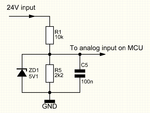
I would use a voltage divider with a capacitor for noise reduction and a zener diode for safety reasons.
I have tried to upload a picture for a simple schematic

24V interface.png

The schematic is for a 5V MCU, and if You need to measure higher voltages than 24V, you can replace R1 with a bigger value. The capacitor should be a poly- type to minimize leak current.

Friendly regards

H.E.Tjelum
 
yes
H.E.Tjelum presented a quite decent solution
I would also suggest the same
 

Thanks for your reply and for the schematic.
I think i will use it to determine if vbat is below 14V.
But what about the 24V unplug? should it be possible to use a digital input to the MCU ?

many thanks regards
 

Thanks for your reply and for the schematic.
I think i will use it to determine if vbat is below 14V.
But what about the 24V unplug? should it be possible to use a digital input to the MCU ?

many thanks regards

You can use a optocoupler like pc817 to detect the voltage is present or not.
 

apart from voltage, a current monitor must also be used to monitor battery condition, sometimes a battery may show correct voltage but under load it will fall below normal, this may indicate a faulty battery.

So for a complete check you should monitor the charge and discharge current of the battery. This can be done using a suitable shunt in series with the battery and using the ADC of the micro-controller to read the charge and discharge values, since the shunt voltages will be very less ( a few milli Volts) a suitable amplifier may have to be used.
 

Hi again

To measure whatever there is 24V or not (meaning 0V) it should be fine to use the same circuit and connect it to a digital input. It is just very important that the 24V have the same reference (GND) as the MCU.
If the maximum voltage at the battery is 14V i would replace R1 with a smaller resistor to have a better resolution. I suggest R1=4k7 for this job.
If the 24V is with a different GND i will strongly recomend a optocoupler solution as nandhu015 also mentioned.

Friendly regards
H.E.Tjelum
 
Last edited:

Status
Not open for further replies.

Similar threads

Part and Inventory Search

Welcome to EDABoard.com

Sponsor

Back
Top