RCinFLA
Advanced Member level 2
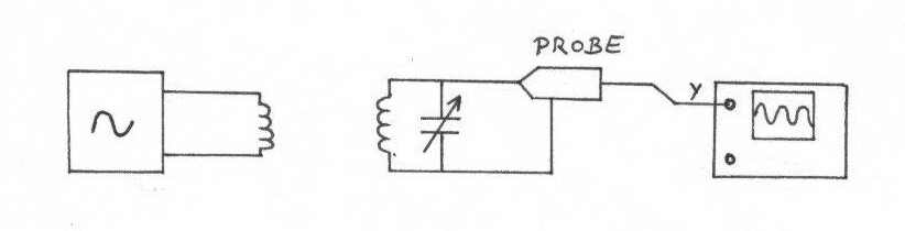
What is inductance value and frequency? Unload Q looks a bit low but until I know inductance and freq won't know for sure. Also show exactly how you coupled into tank to make unloaded Q measurement.
Follow along with the video below to see how to install our site as a web app on your home screen.
Note: This feature may not be available in some browsers.
sorry! my mistake.. I've forgotten to say that I've done these tests with 2 MHz resonance..sorry..
Maybe 1/2*π*√LC isn't exactly 2 MHz in theory, but in practice is the value that corresponds to the maximum amplitude of the 2 MHz harmonic.
Another thing, the generator has high impedance output..
Thanks again for your willingness..
Ok, assuming instruments are 50 ohm. What's 317K?Assuming both the generator and spectrum analyser are 50 ohms you are projecting 317K || 10 pF from each end (at 4 MHz) so you are loading tank with 158k and 20 pF.
On a wild guess, the parallel Rp of the ferrite tank will be in the range of 5k to 15k ohms. If you want to drive it with a ten ohm source then configure a matching circuit to take 10 ohms to 5k ohms.
If your ferrite coil is 22 uH @ 4 MHz then you have +j553 ohms in parallel with about 5k ohms. The series equivalent is 60.5 + j546 ohms. If you add -j546 capacitor (72.8 pF cap) you would have 60.5 ohms real impedance at 4 MHz. The loaded Q will be 2500/553 = 4.5 or BW3db of 885 kHz at 4 MHz. The 2500 number assume 5k due to coil Rp and 5k in parallel due to matching loading.
I suggest you reserve some of the loading capacitance for tuning. Reserve about 10 pF for a parallel tuning cap, leaving 62 pF for matching. Change the 10 ohm to 56 ohms and connect a 62 pF in parallel with 15 pF trimmer then in series to coil. Adjust trimer to get 4 Mhz resonance.
I must confess, I even don't understand the purpose of the calculations.And, my main doubt: my considerations in post #27 are correct or I'm missing something?
The impedance of the unloaded LC circuit in resonance is real, it equals Rp. So which complex part you want to match?Now the goal should be finding the value of a matching capacitor that eliminates the complex part of the total impedance.
The correct formula for Rp is Rp = Q √LC . Isn't it?
In this case Rp accounts for the various dissipative and parasitic effects..
So, what's the RL you're talking about?
And, my main doubt: my considerations in post #27 are correct or I'm missing something?
Thanks
FvM said:I must confess, I even don't understand the purpose of the calculations.
RCinFLA said:For the Q testing you cannot use a HiZ source since there could be a significant amount of capacitance in the cable and output source that would screw up the resonance Xc assumption.