Continue to Site

Welcome to EDAboard.com

Welcome to our site! EDAboard.com is an international Electronics Discussion Forum focused on EDA software, circuits, schematics, books, theory, papers, asic, pld, 8051, DSP, Network, RF, Analog Design, PCB, Service Manuals... and a whole lot more! To participate you need to register. Registration is free. Click here to register now.

help: dimming LED via controlled gate voltage or base current on transistor

Status
Not open for further replies.

NuNDoe

Junior Member level 1
Joined
Jan 19, 2011
Messages
15
Helped
0
Reputation
0
Reaction score
0
Trophy points
1,281
Activity points
1,435
I have a strobing LED that is controlled by a microcontroller via an N MOSFET. The strobing LED is carrying a modulated signal. The microcontroller will pulse the gate voltage of the MOSFET to turn the LED on and off. (see picture)
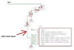
oldstrobe.jpg

A new design requires this LED to have adjustable intensity. Since the LED has a modulated signal, using the common PWM way of dimming won't work. I will have to dim by limiting the amount of current pumping through the LED.

I thought one way to do this is to give a lower voltage to the MOSFET gate --- the lower gate voltage would be the output of a digital voltage divider. However, I don't think I will be able to get the fine tuning of current needed with a MOSFET.
newstrobe.jpg

Can anyone give me some tips for my new circuit? Should I be using a PNP BJT instead of a MOSFET? If so, what are some calculations I need to perform in order to figure out what voltage needs to come out of the voltage divider and onto the base? I am using a digital potentiometer in the new design so that the microcontroller can control the output intensity.

Any advice would be greatly appreciated.

Thanks!
 

If you've got a digital pot, why don't you just put that in series with the LED?

Or you could use the digital pot to control a constant current source which would supply the current to your LED.
 

Digital potentiometer in picture has value for max. current <2.5mA & max. voltage 5V
 

Digital potentiometer in picture has value for max. current <2.5mA & max. voltage 5V
I thought that might be a problem. Also, getting a pot with a low enough value could be difficult as well. I still think the constant-current source would work well; a cheap transistor and 2 resistors and the digital pot. Still, if you don't need too much accuracy, then just using the digital pot as a voltage divider may work just fine.
 

i'm leaning towards the transistor method --- but I need a bit more help with calculating the necessary resistor values and specing out the correct transistor for this application.
the signal being transmitted is being strobed in short bursts --- the LED is module needs to get 2.1 Amps peak current.
 

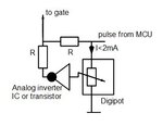
This might work as control circuit via gate.
I think you get the idea in that picture.............

gateinvpulse.jpg
 

This might work as control circuit via gate.
I think you get the idea in that picture.............

View attachment 61002
what's the purpose of that inverter?

I was looking at some of the curves of available mosfets, after drawing the load line on the Ids/Vds curves, I don't seem to get enough control (or resolution) on the output current. I would have to swing greatly over the Vgs in order to get a bit of current difference. Would standard NPN transistor work better than a mosfet in this case? if so --- can they handle pulses up to 2.1A? I'm looking for it in a SOT-23 package or similar, if possible. Needs to be compact.

many thanks

---------- Post added at 08:28 ---------- Previous post was at 08:25 ----------

do you happen to know of any standard digital pots able to handle 2.5A pulsed current?
 

Maybe you can also use PWM to switch the mosfet and a diode/coil/capacitor in the output to provide a mean DC voltage to the LED.
In that case you will also need a feedback system, like a shunt resistor to measure the output current and change it according to the specified target current.

DLC.GIF

Alex
 

thanks Alex, but that topology is basically what standard LED drivers do for CONSTANT CURRENT outputs... that would be fine if my light is simply on. the real problem is that it needs to be pulsing signals with up to 50KHz modulation... having that coil and capacitor will filter those features out.
 

With your PWM modulation the MOSFET is dissipating very little power (that's why people use PWM). HOWEVER, if you start to bias it into its linear region (with reduced pulse amplitude on the gate, e.g.) you are going to deal with added power dissipation. This would also be true of a BJT. And I don't think you're going to find a BJT in a SOT-23 that can handle >2A. You have 12V @ 2.1 Amps==> 25 Watts. That's a lot of power. You SHOULD be able to control the output current from zero to max. (For a MOSFET Id=gm*Vin, so varying Vin will vary the output). The complication comes in because of the non-linear LED.
 

true,operating in the linear region adds extra power dissipation. however for my signal, the worst case scenario is that the LED is pulsed for 30ms then off for another 200ms. So what ever transistor passing the 2.1A current should have enough time to cool down, I hope. can BJTs handle short PULSES of 2.1A if the duty cycle if the pulse is around 10%? (I guess average current would be <210mA)

i will try with both a BJT and mosfet and experiment a little.

remember, i don't have to use this topology for signal attenuation, if anyone can suggest another way I'd be happy to try it out. thx!


one other method i was thinking about is to use an adjustable linear regulator to lower the LED's input voltage...
 

I don't know what your modulation scheme is, but perhaps
you could (say) combine FM (for data) and PWM (for intensity)?
That ought to be relatively straightforward.

You could use a low frequency current mode controlled PWM
letting the inductor stand off high frequency modulation,
the PWM setting the "center intensity" and a high-pass-
coupled data setting the "difference intensity".
 

You have to consider your average power dissipated by the MOSFET. Assume your LED drops about 2V, with your 9.1 ohm resistor, you're going to put (12-2)/9.1=1.1Amps through the LED (Not sure where you got 2.1A). This assumes that the MOSFET is full on. Now, as you control the Vds of the MOSFET to vary the current, the power dissipated in the MOSFET (or BJT, doesn't matter) is:

Id=12-Vds-Vled=12-Vds-2=10-Vds
P=Id * Vds.

If you plot this (or put it into Excel or do some calculus) you'll see that you get a maximum power of 2.75Watts when Vds=5volts. Thus, worst-case average power will be about .275W at 10% duty-cycle; a sot-23 should handle this with proper heatsinking.

******
You know, after all this talk, I would just breadboard this and see if it works. It's not that complicated a circuit; just drive your gate with a signal generator and play with the amplitude and see what happens. Maybe you can have some fun blowing up components.
 
  • Like
Reactions: NuNDoe

    NuNDoe

    Points: 2
    Helpful Answer Positive Rating
You might also look into laser diode driver ICs, which tend to offer independent
control of baseline current (to maintain above lasing threshold) and peak current
(to limit excess power beyond what's needed). These are getting pretty cheap
especially the ones that are slower than leading-edge FO links use.
 

i think you're right --- just gotta experiment with the component and check it out. thx
 

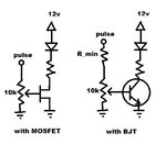
my one other concern is the difference in behavior between a MOSFET and BJT:

with the mosfet, there is minimum gate to source current, rather it's the voltage applied to the gate that controls the drain-source current. therefore the output of the digi-pot sshould be enough to drive it, just may not have as much resolution as i would like. looking at some of the Ids and Vds curves with my load line drawn across it, varying the Vgs by even a few volts doesn't change the Ids by much when it's operating in the linear region.

now with a BJT (i don't have much experience with these as most of what i do has been digital circuits controlling gate voltages instead of base current), i can control the drain-source current (collector-emitter) via the gate-source (base-emitter) current. where I_ce = gain*I_be (i think this is right?) .... is that I_ce the maximum allowable current under conditions of a low (or 0) impedance load? if so, i believe the digitpot circuit needs to be modified with an additional series resistor for current limiting the base-emitter right? (see image)
mosvsbjt.jpg

furthermore, using a BJT, and assuming I want 2.1Amps to pass through and assuming a gain of 100, I would current limit the 5V pulse signal to 21mA right? that is R_min = 5/.021A = 238ohms, does that sound about right or am i doing something absurdly wrong?

BTW, the 2.1Amps is correct but my 9.1ohm resistor is from a previous design, sorry about that... should be about 4.7ohms
 

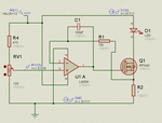
Do you think you could use a circuit like

voltage_to_current_lowside.gif


You can control the output current with the input voltage, you can use the digital pot for the input

Alex
 

Status
Not open for further replies.

Part and Inventory Search

Welcome to EDABoard.com

Sponsor

Back
Top