Continue to Site

Welcome to EDAboard.com

Welcome to our site! EDAboard.com is an international Electronics Discussion Forum focused on EDA software, circuits, schematics, books, theory, papers, asic, pld, 8051, DSP, Network, RF, Analog Design, PCB, Service Manuals... and a whole lot more! To participate you need to register. Registration is free. Click here to register now.

[SOLVED] Daft question? Can mount multple PIC's on top of each other and just separate MCLR's?

Status
Not open for further replies.

polo-g40

Full Member level 2
Full Member level 2
Joined
Jan 12, 2011
Messages
143
Helped
36
Reputation
84
Reaction score
42
Trophy points
28
Location
Gone
Visit site
Activity points
0
Daft question? Can mount multple PIC's soldered directly on top of each other with just separate the MCLR's lines turning on one chip at a time under some other control?? I wonder has anybody tried it???

The project I am thinking of (an LED Display) takes some shoe-horning of coding and would be easier adding multiple processing units and having one to "select" the active chip..! It would be Just as easier or easier than adding memory EEProm to add another 16f88. It would make an easy selection process (using a switch to start), but would one chip's output be interefered with by any of the "off" units...? I am using a 16pin 2port chip, and using RA0 & 1 and RB0 to 3 (All drive low, portB drives high too)...

I am likely to give it a go in one form or another unless anyone has tried it, wether it be a separate bit of veroboard or tagged on top of each other, but has anybody tried?? I could try keeping a processor to keep Low-Voltage-Programming a single PIC but that seems a bit ambitious!

Only a hobbiest, but fun!
Kind regards
NEAL
 

I have done it (piggy-back) with old computers to upgrade ram but they had tri-state IO and address pins and it was simple to run the enable pin to the memory bank decoder chip. In the end it would be easier to upgrade the processor to something that can handle the job.
 
. In the end it would be easier to upgrade the processor to something that can handle the job.
ah, that was quick... My 368byte A. I. could have predicted that one coming! :)

Anyway, I'm gonna try it.. It's a 1 second solution to a not-really-a-problem... Hobbies are like that! For £2 odd, I can make a bedroom light do slightly more... It's not incredibly worrying,

but!!! (
[Lol]
What if I could make a (sort of male?) PIC that is able to re-program "impregnate" another similar PIC and force bits of its code onto another, similarly coded but "Female" chip? :) . Write a nice display demo that had sections of it interchangable functions and make it "impregnate" by overwriting just those specific code areas written to be able to swap and accept changes.. It's not giving birth, its "Forced Mutation", but giving working, but differing results of the two chips "Coming Together"!! I could keep "Mating" them and keep the results I find most entertaining!!!! :) Sound familiar! :)
I'd be fun to write a simulation of it though!!!
[/Lol]

This is what I need it for, so a £2 (and I've got one in a box) chip addition might be well worth the effort!!! Especially on veroboard!
best regards! :)
NEAL
 

Hi Neal,

Why not implement I2C or SPI on the available SSP module? There are some fairly large EEPROMs available for both protocols. And if you need more digital I/O there are port expanders available as well.

**broken link removed**

BigDog
 
  • Like
Reactions: FvM

    FvM

    Points: 2
    Helpful Answer Positive Rating
Why not implement I2C or SPI
Yeah man, I was thinking that... I've got to stick to verboboard remember though buddy, I'm only dossin at home! I miss the days of test equipment!! I do have the sim-like chips on cards out of some RICOH toner cartridges I think were 8k... But its not just space-space, its program space, and things stack up when you add them together more then if I can keep it separate.. Like loading another program through ICD, but just simple... I imaging it might work, and am willing to try eh!! I'm doing all this to learn all new stuff and its I'm having fun so far, many thanks Bigdog, you have been a great help matey..!
Because my next thoughts turn to using linked serial-ports (using SSP) just Tx to RX, one chip to the next, sending the last value of the "table".... If it could be that ssimple, and fast enough, an infinite line of these panels doing osciloscope would be possible.... If I wo the lottery my room would be one big sprial of them added together... If I wanted to know what music was playing yesterday, I could have a look at my display,! :)

Jolly jolly but determined! :-D Neal
(thanks BigDog!)
Kind regards
NEAL

---------- Post added at 21:21 ---------- Previous post was at 21:20 ----------

ps My PIC24 Wi-fi integrated demoboard Still Isnt Here!!! Pain in a** waking up everymorning ready for post,..!

---------- Post added at 21:35 ---------- Previous post was at 21:21 ----------

Would you believe, I2c is what bought me to this road!!!!!!!!

I had a samsung printer that can be "chipped" (kit off ebay) to take any old toner... I did mine, worked perfect..A friends, it all went wrong, samsung it turned out had stopped just "write protect" in a new firmware version!!! Somehow I screwed it up, and a £150 printer was knackered... So I got another blank chip off ebay and looked and fouind "PonyProg".(an excellent EEProm programmer).! If not I was looking at writing I2c (from the protocolsheet) for a Maplin's USB relay board I had, but ponyprog saved the work!!!

(For my dad as a fun project) I then had to find a way of integrating a stepper motor into an antique "Ticket Clock" and came accross the Velleman PIC programmer and demoboard from Maplin's which had a 16f627 in.... That was blown in minutes... So I bought a load of 16f628's and made a clock that ran fromt he intenal clock in hours... I'd not looked at PIC since Uni 15 years ago, but it was easy enough in C... I then realised I needed a Xtal, did all that, then I though I'd add and RTC... I got the RTC chip to do one second ticks of an LED as my 1st "I2c by hand.. It would only work after setting the time!!! Using a BYVAC I2c-Rs232 converter (Excellent!!!!!) I managed to find I needed to send Stop-D0-09-01-0 etc (DO if I left the address pins high!) got it to flash, and I spent a while on the 16f628 to get it to to write these over I2c..!!! It worked, but the timing was really crap!!! I was better using 4Mhz!!!

The clock was quite a nightmare, sometimes there were 11 "stepper ticks" bettween minutes flapping, sometimes 15, sometime 12, so I ended up sat there counting them!!! And it worked too.....

But, I was using up 16f628's, and ordered a few 16f88's just because of the A-D fun potetial, so I've got a few...>! If I have one with one "effect" on, one with another "Effect" on, I could mount them on separate veroboard, and just switch the whole lot off, but I am sure I'll manage, we'll see!!!! The A2D bias might shift is an imediate thought... :)
NEAL
 

Yeah man, I was thinking that... I've got to stick to verboboard remember though buddy, I'm only dossin at home! I miss the days of test equipment!!

I'm not familiar with the Verboboard, however setting up the SSP is fairly straight forward:

Example code for I2C, routines for PIC16F877 to write to the 24LC01B EEPROM, using the PICDEM 2 demo board from Microchip.

Example Hi-Tech C code for I2C, interfacing to Microchip 24LC01B non-volatile EEPROM and Dallas Temperature sensors DS1775 and DS1721

Serial EEPROMs are fairly inexpensive as well.


Because my next thoughts turn to using linked serial-ports (using SSP) just Tx to RX, one chip to the next, sending the last value of the "table".... If it could be that ssimple, and fast enough, an infinite line of these panels doing osciloscope would be possible....

Definitely doable.

I2C communication between PICs


Hope the info helps in your adventures,

BigDog
 
I'm not scared of I2c, I've got headers that'll bit bang it if I ask too and like I say I learned a lot with samsung EEPROM writing and sniffing and stuff!... But it is un nessesary for the mo I think, just async be ok surely...!!!! I'll let you know when its wired up and testing buddy!!! :-D

Veroboard (TM) is a lump of pre-drilled fibre circuit prototyping board, that has copper tracks vertically from top to bottom... Sticking an IC in means cutting the tracks between etc..! :) Its a lot of fun way of making circuits up easy at home... Look it up on google image if unsure, but it shows the level of technical equipment I dont have!!!

Kind regards
NEAL

---------- Post added at 21:59 ---------- Previous post was at 21:58 ----------

And my 16f877 PIC16 DemoBoard II has an SPI and an I2c eeprom I've played with...!
NEAL
 

Veroboard (TM) is a lump of pre-drilled fibre circuit prototyping board, that has copper tracks vertically from top to bottom... Sticking an IC in means cutting the tracks between etc..! :) Its a lot of fun way of making circuits up easy at home... Look it up on google image if unsure, but it shows the level of technical equipment I dont have!!!

Ok,

I am familiar with Veroboard, but I did know if Verboboard was some something different.

The I2C libraries I posted the links to above were written for the Hi-Tech C Compiler. They should be able to step you through the process of configuring the SSP module for I2C.

Most SPI or I2C are small package DIPs and easily implemented on a Veroboard. Practice SPI and I2C with your Demoboad II and you'll see the implementation of either protocol is fairly straight forward.

BigDog
 
I've used I2c an awful lot, I have my own libraries... I should be using the SSP module to talk to the LED panels but my "Not The Beaten Path" approach is about to give me 4 lines at once too!!
 

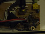
P1000642.JPG
this is what we're looking at buddy!!!
If I can just stick on another 88 its a £2 upgrade. Even if I have to use a multipole switch to swtich more lines..! I really don't need anything but more effects, its no PI calculator!!!
Best regards
Neal
 

I haven't tried it with uC's (just memory), but sure would love to hear back to see if it works.
Sometimes we do things just to see if they can be done.

Let us know how it works out.
 
Sometimes we do things just to see if they can be done.
Exactly matey!! Many thanks... I'm just progging up the next chip to try it on but bedtime looms!
I was going to ask about multicast TTL serial next as well, but thats a few stages on yet! I think we'll know I'll make it work somehow,its just how many bits do I have to isolate? GND and Vpower might be requisites, but I let you know tomorry.! All I'm going to do is a slower version of whats on there now, so I've got a timebase selector.. Chip 3'll possibly have an air-hockey game, paddle driven by the big POT you can see in the picture that sets the a2d bias level..!!
Kind regards matey! :)
NEAL
 

ah, that was quick... My 368byte A. I. could have predicted that one coming! :)

I'm all for hacking it just for fun! ( I did something like that years ago with a Atari ST with a piggy-back cpu for multitasking because you couldn't completely virtualize a 68000)
Popek and Goldberg virtualization requirements - Wikipedia, the free encyclopedia

Some old software I wrote for the ST multitasking in a now dead programming language.
**broken link removed**

But for me as I get older the time wasted in a neat hack can't be gotten back and leaves less time for making something that's bulletproof when running somewhere other than a workbench.
 

I love the kernel!!! I used Minix a couple of times for fun but I'd have loved to have tried yours! Many thanks :)
I love my ST..! I had a pigyback NEC V30 (x86 clone) for my "Now thats "PC Speed"" PC emulator!!! I cam accross the bootdisk for it yesteray in a box with DevPak and GFA Basic..! I did love 68000!

NEAL

---------- Post added at 08:33 ---------- Previous post was at 08:32 ----------

And the "Piggy back PIC" worked..! :)
NEAL
 

I did something like that years ago
We are from an era of computers when programming really was for fun the same I recon! As soon as you say Atari ST and multitasking you gain my respect straight away!!!! There have been many steps in my life and mastering VBL and HBL on the ST was I was one, debugging 68000 (and ripping out copy protection), superb fun! :).....! :)

The driving thoughts behind this thread is that I am not looking for super-computing with the questioning in the topic, just simple upgrade options for a bit of fun kit! I was hoping to be telling you now how an 8 pin 12f765 was running my digital-display-world having spent half the day going through my chip stock to find the 12F chip I've been saving was not a runner... I have found I have 3 working 88's, lots of 628a that ID OK and program up but don't give any outputs out of any ports (and a 88 the same, probably "Pre-addition-of-a-zenner-Clock-Steppermotor-Driver" chips), and one 628 that did work..

Piggybacking these did make them work as normal (One dodgily tied to GND while the other to ICD) but one I ran from it's INTOSC and left its pins away from the OSC in and out lines. It means my bedroom light can now flap 100x4 letters accross a display funkily, or I can have it set as an osciloscope Sound-to-Light-box, without pulling out an ICD lead or losing something by co-existing them..! Job done, superb! :)
NEAL


Hopefully, a PIC24 wifi and CF card integrated webserver demoboard will arive in the post real soon and I can try having 256K Program flash, and 16kb of Ram, and hopefully some LED fun with... I'm wondering if I can read a scart signal. I'll need to multiplex CS lines too if it goes that big..
 

Good job. I found one of my old DIY rom/ram cards from a 1970s 8080 project with piggyback Intersil 2114 memory chips. ( they still make a version of them! **broken link removed** )

CLIP0060 | RAM/ROM Board

I might just make it into a clock with a pic18 chip and use a 2114 as external memory via a data port.
... one day.
 
I love the memory board!!! I was Lol'ing along with the voice in the background in the video, thank you, made me smile!!!
I did my apprenticeship making radar, and it reminds me of the stuff I used to work on! Its amazing what an 8080 can do I know!!!

Many thanks,
NEal!!!

ps
I might just make it into a clock with a pic18 chip and use a 2114 as external memory via a data port.
... one day.
You are my kind of engieer mate!! :)
 

Oh my word! The 24FG256 board has come! I've got the supplied code working, I can now tell the temperature in another room via an adhoc wifi networked web-page! And switch one of 5 LED's on or off!!! Imagine that for £30 in the 70's! We'd have well past the singularity by now if that was the case :p
NEAL
 

Yaeh man, concept proved.....! :)

On one chip I am using RA0 and RA1 (easiest ports physically for the veroboard setup I've made 1st, I had to bit bang the SPI) as the data and clock lines (for the LEDs), and basically the other chip is plugged in on the spare port at the other end of the panels, with its CLK and DATA ports (This chip I am using the SSP module so I'm on RB1 and RC4 (Proper SPI ports) common to the 1st chip's ones, as well as the 4 CS lines (1st chip RB0-3, 2nd chip RA0-3)..

So, I am happy, and I've tested something I've wanted to know for ages!! Thanks EDA for the thinking space!!
:-D:-D
NEAL

With a simple dual-pole switch, I can gnd the MCLR of one chip and release the other (CAPS Required for smooth switch-action) and have 2 different displays demo's set up for only a few pence...
 

And one has stopped working inexplicably.... Hmm, not the result I was after but a result all the same... I can do a similar thing by manually disabling one board first and then start the second, but a 2pole switch I think is just a leap too far...
I've lost a 16f88 (I'd bury it with full honors if that was normal) but I've learned something so its all good stuff... :)
Neal
 

Status
Not open for further replies.

Similar threads

Part and Inventory Search

Welcome to EDABoard.com

Sponsor

Back
Top