Continue to Site

Welcome to EDAboard.com

Welcome to our site! EDAboard.com is an international Electronics Discussion Forum focused on EDA software, circuits, schematics, books, theory, papers, asic, pld, 8051, DSP, Network, RF, Analog Design, PCB, Service Manuals... and a whole lot more! To participate you need to register. Registration is free. Click here to register now.

Help needed for halogen torch project.

Status
Not open for further replies.

grahamt

Newbie level 4
Newbie level 4
Joined
Aug 29, 2011
Messages
6
Helped
0
Reputation
0
Reaction score
0
Trophy points
1,281
Activity points
1,346
Dear all,

I own a powerful halogen torch which is designed for mountain biking at night. The torch comprises an Li-Ion battery, and a 'light unit' where the halogen bulb is housed, and a cable to connect the two together. My project has been to make a second battery so I'm not just relying on one.

Specifics are:
Original battery is 11~12 volts, 2200mAh.
The halogen bulb is rated at 10W and 6V.

I've made the new battery from two remote-control car batteries. It is made up of nine 1.3V 4700mAh cells connected in series, and in total gives out about 12V as required. I have charged up the 'home-made' battery successfully and connected it to the light unit and it all works!

The problem is that the light unit is getting quite a lot hotter when using my homemade battery compared to the original battery. The only reason I can think of is that the original battery might have a resistor inside the casing to limit the current drawn by the halogen bulb. Could this be true?

What would I need to do to work out the rating of the resistor I need?

Any assistance would be brilliant!

Graham

---------- Post added at 18:09 ---------- Previous post was at 17:28 ----------

Just finished testing the new battery. The home-made battery lasts for approximately 2.3 hours, so a bit less than the original. But the light unit gets too hot to touch, only when using the homemade battery.

Why are the two batteries running for almost the same amount of time and yet one is 2200mAh and the other is 4700mAh? Is this the reason my light is getting so hot? Am I drawing too much current and it's just dissipating as heat?

Thanks!
 

As the lamp is 6V, and your battery is 12 V, there must be a circuit present that converts 12V to 6V. This can be a switched mode circuit, but also a resistor (that will become hot).

Can you measure the actual voltage of the original battery when the lamp is giving lightl? Are you able to measure the current consumption for both cases (that is original and home made)?
 
If battery packs have same voltage , 4.7Ah battery should give double lightning time compared to 2.2Ah.
When times are about equal this means 4.7Ah gives double current. ( It means more light , but double heat.)
Assuming , battery packs are Ok and full loaded.
You can check , what is happening, by measuring both packs , thisway..............

Meas_Lamp_Unit.jpg
 
Thank you for your replies.

Hmmm. I have tested with my multimeter:

Original battery, light ON: 1A current just after the battery, 10.5V across battery, 3.3V across bulb.
Home made battery, light ON: 0.9A current just after the battery, 11.4V across battery, 3.2V across bulb.

This was only done using a slightly charged home made battery. I'll give it a good charge and see if the measurements are different. It seems that the light unit only feeds 3.3V to the bulb and doesn't use the full power. Must be to spread the charge out and give a longer running time?

I will also check the current at the bulb once the battery has charged.
 

Hello,

There must be something wrong...

You have a 10W, 6V halogen lamp. If there is only 3.3V across it, it will not produce the expected light output (rather red then white light).

It seems lots of energy is wasted (into a resistor?), as the input is almost 3W.
 
Now when i see your measured values .
Lamp unit has somekind of voltage regulator ,maybe not only resistor, when you measured 3.3V and 6V lamp was connected
and shows brigth light. ( I guess your meter show some DC value, but there can be PWM regulator circuit ie. chopped DC-current
not pure ac and not pure dc).
Both batteries give about same power (P=U*I) 10VA
Because we know nothing about the circuit ,one reason can be that 4.7Ah battery has higher voltage, causing higher power dissipation in regulator.
Stabilating circuit can be also current regulator.
If additional heating is caused by higher voltage, it can be tested by connecting 2pcs 2A diodes in series to lamp unit ( this makes inputted voltage 1.5V lower )
or take out one cell.

KAK


Hello kak,

You are right, if you chop 12V with 25% duty cycle, you have 6 Vrms. A DC voltmeter (with an average measurement) gives 3V.

It also matches his input power (0.9A*11 = 9.9W).

Thanks for the hint!
 
Ah I think I'm following. So do you suggest that the problem might be solved simply by reducing the number of cells in my home made battery from 9 to 8? So I'd be inputting 1.5V less. I can try it easily and see what happens.

Just to confirm, there is a small circuit board in the lamp unit with some components on it and not only resistors. I don't really want to take this apart or modify it.
 

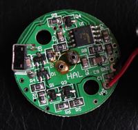
Only because of the interest, can you send few pictures of circuit board so that we can see the components. (If possible)
 

Sure I can provide a picture. For more info about the circuit board, I know that it has a two-power setting, and the switch on the left of the picture cycles between the two power settings. If I hold the switch down the lamp turns off. There is also a feature called 'soft start' which turns the halogen on gently to prolong bulb life. And the other feature is a low battery warning - the light flicks off briefly every 20 seconds or so when the battery is getting close to empty. This flickering gets faster as the battery gets closer and closer to being empty.


So this would explain the features on the board, I suppose.

Thanks,
Graham
 

It looks like the small SOT23 transistor Q4 does the switching from the lamp to ground (and the lamp is connected to Vplus). I coudn't trace the SMD marking.

Where does the heat come from? I can hardly beleive that Watts of power is dissipated into this PCB without frying components. If you can operate the lamp without casing, you may check hot spots (be careful to avoid blisters).
 

I have checked the PCB while the bulb is on for any hot spots and there are no components which are very hot. The whole PCB gets slowly warmer from the heat of the halogen bulb. I suspect that the source of the heat might just be a gradual build-up from the bulb. The light-unit takes about half an hour before it gets too hot to touch, which to me suggests that it's not a component but simply the heat coming from the bulb.

It still doesn't explain why the bulb should be hotter when using the home-made battery though. I'm just about to test the battery with 8 cells now.
 

So even after running the light on full power with 8 cells instead of 9, the light unit still heats up and after about half an hour it is too hot to touch.

My plan is to just leave everything as it is. The reason I'm not too bothered is that when I'm cycling, the light is only on full power for about 10 minutes at a time, then it is turned down to 50% to save battery. So I'm confident there won't be any problems with overheating. I'm going to continue to test it just in case though.
 

Hello Graham,

Do you notice any difference in light output when operating from your "home made" battery? Do you have some means to measure the actual temperature rise for both situations? The reason for this question is that in both situations, the input power is almost same (based on your own measurements. The difference is less then 500mW.

What about the temperature rise of the battery packs? If there is significant resistance in the original pack, the output voltage should drop during load, and you should notice increase in temperature.
 

Status
Not open for further replies.

Part and Inventory Search

Welcome to EDABoard.com

Sponsor

Back
Top