Continue to Site

Welcome to EDAboard.com

Welcome to our site! EDAboard.com is an international Electronics Discussion Forum focused on EDA software, circuits, schematics, books, theory, papers, asic, pld, 8051, DSP, Network, RF, Analog Design, PCB, Service Manuals... and a whole lot more! To participate you need to register. Registration is free. Click here to register now.

de-dp14211 - Sure-electronics-demoboard startup code available.....

Status
Not open for further replies.
Both the camera I have to scrap are Samsung's..... It came from a "special needs" college I do a bit of tech-help for in a box of broken stuff I accepted as sort-of pay! The fault seems to be that nothing turns on! It was dropped aparently.

I have no idea what's inside it yet, but I should have in an hour... I'm desparately hoping for some form of recognisable chip, hopefully with SPI or I2c, but maybe I've got a bit ahead of myself..
Definately too much for me, but I'd have loved to be able to use the screen, I've been looking at the Microchip Graphics Designer visual studio type thing for embedded. The whole lot might be fried or I might not work it out, but its keeping me busy till the 24webserver comes..!

Best Regards
NEAL

I've also got a Compaq KVM switch from them, I've took to bits but there's nothing I recognise chip-wise in there!

The reason I got all this was that I spotted that all their new PC's had the same mac address after the lad had a week of fun!!
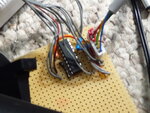
 

The camera chip has a couple of wide tracks on its ribbon, power presumbly, there is a bank of 16 and a bank of 10 pins that look like address and data but its just a bit too small to see to do anything with, I was just too confident! I suppose I was hoping for an I2c camera like the one out of a NintendoWii I've been reading about..

Neal
 

I had some 16f88's lying around, I kept blowing up 628's making a digital mechanism for an "antique clock"! (I'll show you one day!) and last time I ordered 10 16f88's which have been lying around... I didn't realise they have twice as much memory as the demoboard's 723, Usable SSP, and quite quick (with a Xtal though)... I got 88's for playing with the A2D...

So I am thinking, for about £2 each, I can stick one on the back of each panel with the "Rain" effect I've done... They can be fully autonomous then,..!

Just thoughts matey
Many thanks
Neal
 

Oh my word, I have had some luck!!!! Despite my thoughts of leaving the keyboard alone for the weekend, I've managed to, just a moment ago after *hours* of tinkering, and trying everything to get round certain problems, I have 4 single color 8x32 panels running off one of my 88's with a prety lame display on for now, but its there!!!...!!!

Problems being..... Existing programs running from startup (with no MCLR set) on some pic16's (628a's especially) means that half my "playing with" stock of pics became almost useless.. (Until I found that the 88's in a similar state could be poped out and back in their sockets mid erase and that would cure all programming problems!!!

I got a reasonable demo program written quicky and spent hours to find the 88 I was trying would would only run at 32khz internal, any attempt to change OSCCON would just lock it up... It did take * LOTS * OF Experimentation to find the the OSCCON problem.. Plugging the chip into another demoboard with a crystal on it showed it flashed the control lines a lot quicker when set to Xtal mode..

Then I found another chip, that worked properly!! All the ports flashed when I tried a portflash demo, so I soldered it in hoping all would work.... What I thought was the same code had no effect on the screen, even though the DAT and CLK lines were flashing and the CS lines were... In desparateness at 3am I copied the code off the 32mhz only chip onto this one, and YEHAAA!!!
SO the chip worked, but the code is for 32mhz IntOSC. All I needed was a crystal and I've got at least one (or two probably) fully working chips...! I had looked to see if I had an xtal but didn't have much hope, but this morning I went through a bag of resistors trying to pullup the CS lines "by hand" just in case, and I came across a resonator and couple of caps... I genereally buy more than one of everything small when I get stuff so thankfully I must have once..!

But, again, now I have a working setup to prove the board
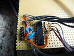
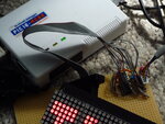
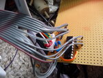
MEMO0017.JPGMEMO0021.JPGMEMO0018.JPGMEMO0020.JPG

All I have to do is get back to the code that I've had working........!!! Not this moment though, but I want to see how my oscilloscope looks with double the length.. It might be too slow (but I think I can have the PIC at 20mhz so might not be too bad), but the extra memory of the 88 over the 723 means I can have at least twice as many panels...

Here's the vid,
Kind regards mate, thanks for listening :)
Neal
 

Yes Zsolt!! Thank you! Hope the flat is all OK!!

If you thought that was good, I have just found a 23Mhz crystal on a board out of an old printer, stuck it in place of the 4Mhz one and it is flying, presumably at high speed.....

I've just moved the osiloscope project over to it, the 88 has loads more memory, and now its up to speed I'm thinking of 8 (8x32) panels in one line!

I've got code to share when your decoratings done matey.... Just a little change to that demoboard and I've got loads of sound-to-light stuff for you to try..!

Kind regards Mate :)
NEAL

ps BigDog, hope weather is ok at your ends...
 

I have had some luck these couple of days....! :) Finding a xMhz xtal kit I didnt know I had, then finding a 23Mhz crystal, and some working PICS....! :)

I've been thinking how I need an audio amp chip for this 16f88 setup, the audio level from an ipod isn't quite enough to drive the DAC, especially now the chips running 5.5times faster, and tripped over a board on my floor that had from came from inside a flatscreen (I get given stuff to pull to bits a lot) that's got a "TDA7496L" 18pin ch on it... It was about the only descrete IC on the board, and was close to the headphone socket.. I looked it up and its "TDA7496L - 2W2W AMPLIFIER WITH DC VOLUME CONTROL - STMicroelectronics"
Its a proper size chip that'll slot in the veroboard setup perfectly I hope.
To try and get a bigger shift on the osciloscope display, I tried doubling the "1/2vdd tying" ressistors (10k to 20k) and a massive decoupling capacitor but the cap took over 10seconds to discharge the "knock" when I plugged in my ipod! No matter how big the cap is, I can't get enough signal without plugging it into speaker outputs.
Hope all's well for everyone
Neal

---------- Post added at 21:00 ---------- Previous post was at 19:38 ----------

This is all just for fun, I'm not currently employed so have little in the way of technical outlets and appreciate the space to document some thoughts... :)
All of this is in my home, on a pc thats had no case on, a tradition of 20 years. Anyone with thoughts please feel free to point me in directions considered fore-trodden. Others may ay have other things to worry about, but here here are the videos of the first decent 23.5MHZ 16f88 coupled with 4 LED (8x32) panels.
Same old style on the code, wavey writing!! :p , but on the left you can just make out a lump of veroboard and a chip.. I've had to slow the code down it was ripping along at some speed.
I was considering the advice of a friend to buy a 16F887, which I appreciate. I have only moved onto the 88 for a bit because "I had one". I wanted to try and make something I can say I have made "post op", Lol.

I believe this 88 is at the next level now where I want to be driving these Bi-Color displays, and I think the best way will be by modifiying this setup so I have individual DAT lines going to each LED panel's Dat inputs, but sharing the clock still. Serial control of more than one bank could have been tricky so it gives that way of "selecting the destination" en mass. PORTA is a bit cluttered, it has the crystal on 2pins, MCLR and AN3 I am using for the scope input.. But I can try on 2 of PORTA to start... I am saving PORTB for the thoughts of any inputs, SDO and RX are on the same lines (RB2) so my thoughts of multicast ttl serial control one day are probably requiring more pins.

but without seeing being able to visualise results of having neighboring bits in "realitiy" that will be at least 8 (red) or 32(BiColor) dots apart I am having trouble imagining the logic that would be how to display the graphic data viewably!! We'd be back to framebuffering again, passing 2/4 or 8 bytes at once to a modified version of the current "sendBitsOutSPILike(unsigned char out)", modified so it sets all the DAT lines all at once (on one port I would hope) for one CLK pulse. I think it may be similar to the atari st's "BitPlane color-encoding" but without seeing the results I've got little chance. . I have used the SSP Ports for other things (I suppose whats on there is movable, SDO and SCK) but using code to drive the data sending means more data in parrallel will be quite an easy transition..!

But the Parallel port latching on the 16F877 would be perfect too, use all of portD and the clock, all in hardware I am sure..!

Regards & Thanks for space
NEAL
 
[q]I've been thinking how I need an audio amp chip for this 16f88 setup[/q]
How thick am I? There is a VREF input on the PIC!
Neal
 

So, the ADC VREF+ input is on a Potentiometer, set to 1v., the Y Offset is also now on a pot. IPOD drivable to the full range now!! Anthing the ADC reads between 120 and 134 now gives blank, so music off means light off!!!

Well chuffed
This is a vid of the *final* results (I've "stuck" in an outdoor lightbox I've had saving for years) with Comedy-Audio input :-D

This is the funniest thing on the radio for years! Listen out for Norma at the end!! LOL indeed

 
Last edited:
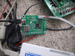
P1000652.JPGP1000655.JPGP1000654.JPGP1000653.JPG
PIC24 boards here!! I've just had to register to download C30 and its installing now!!!!
I love these people's kit, I recon I'll have an LED display on it today, I can tag into the ttl (cmos?) serial header connections that go
 

[q]all your post are really amazing!!! [/q]
Many many thanks, I'm smiling now... I hope we'll do some good stuff on your kit Lloydi, you'll be able to do equally as good I am sure!!! Any ideas you have to make them better let me know!

These are all relatively simple and with a sit-down with you we'll get you coding these no problem.. I'll set up a team-viewer session if you're up for it and webcam you you can have quick practice on mine so you can se the results... As for algorithms etc, there are not many, and only very simple, because adding the maths library (using %) suddenly doubles the code-size!! The "sine-wave text scrollers" aren't strictly "sine".. I add one to the "shift" postition (each line) until it reaches "SinMax", then decrements instead until reaches 0, then increments again... By changing the "Start of sine" position but not moving the text, we get the nice flag-wave effect... We'll get it into your code soon I hope! :)

Kind regards & Thanks
NEAL
 
Yehaaa! A PIC batch-programmer speicalist in the UK wants someone to come in on-and-off and solder small component boards etc... This is making me think its maybe a bit more possible to get a PIC VGA Controller made for my own uses... Are there any ideas floating?

Kind Regards
Back :)
NEAL
 

Status
Not open for further replies.

Similar threads

Part and Inventory Search

Welcome to EDABoard.com

Sponsor

Back
Top