PA3040
Advanced Member level 3

- Joined
- Aug 1, 2011
- Messages
- 883
- Helped
- 43
- Reputation
- 88
- Reaction score
- 43
- Trophy points
- 1,308
- Activity points
- 6,936
Follow along with the video below to see how to install our site as a web app on your home screen.
Note: This feature may not be available in some browsers.


Thanks Mr:ckshivaram
while we continue this
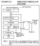
Generates a Pulse-Width Modulated (PWM) signal on the CCP1 and CCP2 pins
Duty cycle, period and resolution determined by the following registers
PR2--------Period Register
T2CON-----Timer2 Control
CCPRxL-----Duty Cycle Register
CCPxCON---CCP Control Register
what will be the next


The algorithm to produce the necessary PWM waveform is simple in this initial test version: it is designed to produce a basic inverter allowing the hardware to be prototyped. The firmware functions as a pulse-width modulator (PWM) producing a variable pulse ranging in width from 4.1 mS to 8.2 mS. The width of the pulse depends on the output voltage required. A wider pulse produces a higher output voltage while a thinner pulse produces a lower voltage. By sensing the AC output voltage of the inverter the MCU can adjust the pulse width accordingly to produce a nominal output voltage of 115 VAC. The PWM is required in the first place to compensate for loading of the output. If the inverter's pulse width were originally set to give an RMS output of 115 VAC and a large load were applied, the output voltage would drop drastically essentially producing a brownout condition on the load. The PWM must compensate for this by increasing the pulse width as more load is applied. In essence the system operates as a voltage regulator keeping the output voltage constant as loads of varying degrees are applied.

Hey man
Today i am also here to ask aabout step by step pwm tutorial . I dont know that where do u want to use this but i want to use it in inverter . I want to learn 50 Hz with pwm control . Actually what i want to say is a fixed volt ups . as the load increased on the out put of ups the pwm increased as the load decreased the pwm decrease to make the voltage fixed at 230 volt from 12v input. Just like TL-494 or SG3524.
Can anybody help me to do this with modified sine wave or sine wave????????


Hi All
I read all step by step and now I am trying to configure PWM
BSF TRISC,2 ;Configure pin as input
BCF T2CON,TMR2ON ;turn off timer2
CLRF TMR2 ; Clear Timer2
I think now need to Set up Period and Duty Cycle
Am I right?
If I ask, why we clear TMR2


Hi
here PR1 + 1 I think 1 mean constant


the above paragraph says "Up to 10-bit resolution is available"
What is this resolution
can somebody explain it