Continue to Site

Welcome to EDAboard.com

Welcome to our site! EDAboard.com is an international Electronics Discussion Forum focused on EDA software, circuits, schematics, books, theory, papers, asic, pld, 8051, DSP, Network, RF, Analog Design, PCB, Service Manuals... and a whole lot more! To participate you need to register. Registration is free. Click here to register now.

DC/DC buck converter power efficiency problem (voltage mode)

Status
Not open for further replies.

naeim29

Newbie level 5
Newbie level 5
Joined
Jun 2, 2011
Messages
8
Helped
0
Reputation
0
Reaction score
0
Trophy points
1,281
Location
sweden
Activity points
1,361
I'm designing a circuit of DC/DC synchronous buck converter for low power application(voltage mode) in 65nm by Cadence tools,I finished the circuit design and it is able to step down 1.1 V to 400 mV(Reference voltage),but its power efficiency is not good(around 35%)I read so many papers to find how i can optimize the power efficiency and I did so many changes for example sizing of switch transistors,changing frequency,changing driver structure...but still its power efficiency is too low!!!in one paper i found that if difference between input voltage and reference voltage is high the efficiency will reduce but I'm not sure how much it will reduce!I will be so appreciated if someone can help me to how I can increase efficiency!thank you so much!
here is my results so far:

Average Input Current : 103.7 uA
Input Voltage: 1.1 v
Average Output Voltage: 399.8 mv
Average Output Current: 99.9 uA
Switching Frequency: 5 MHz
Settling time: 20 usec
voltage ripple: 3.97 mv (0.99%)
current ripple(peak to peak): 993.4 nA (0.99%)
Power efficiency ([Pout/Pin]%): 35%
 
Last edited:

Decompose the problem into a set of -inefficiencies- (conduction loss in
HSS and LSS, switching loss, overhead loss, ripple losses in the caps,
series loss in the inductor, etc.) and you will know what to attack.
 

Decompose the problem into a set of -inefficiencies- (conduction loss in
HSS and LSS, switching loss, overhead loss, ripple losses in the caps,
series loss in the inductor, etc.) and you will know what to attack.

Thank you for your replying,but I have considered all of your suggestions before,like switching losses,conduction losses and so on,also i should mention that my inductance is ideal component.in some paper i found that if the output load(Iout) is low it's better that use current mode control instead of voltage mode,I'm wondering if it could be one of the reason of my low efficiency!!!
 

I mean, you must pick off the dissipation for each of these terms, across
a few cycles, so you can get a quantitative idea of what's wrong. You
should not be wondering, but measuring (in simulation).

One other thought occurs to me, which is to look at loop stability. Any
oscillation (subharmonic, or loop) will "slosh" current into and out of the
load, which is very lossy.
 

Current mode or voltage mode will not lead to obvious efficiency difference.

Thank you for your replying,but I have considered all of your suggestions before,like switching losses,conduction losses and so on,also i should mention that my inductance is ideal component.in some paper i found that if the output load(Iout) is low it's better that use current mode control instead of voltage mode,I'm wondering if it could be one of the reason of my low efficiency!!!
 
Hi friend,

Sorry I have no suggestions for your problem, you seem to know more about it than me.
I am designing a motor speed controller, and will be using current mode control. However I am unsure of how I will be closing the loop to make it stable, How did you go on about using voltage mode control, i.e. selection of components? I have looked at rather complicated examples of using small signals models for such designes but I want to avoid that if I can.
Your help is appreciated.
 

I mean, you must pick off the dissipation for each of these terms, across
a few cycles, so you can get a quantitative idea of what's wrong. You
should not be wondering, but measuring (in simulation).

One other thought occurs to me, which is to look at loop stability. Any
oscillation (subharmonic, or loop) will "slosh" current into and out of the
load, which is very lossy.

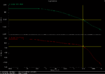
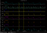
Thanks for your replying,one of my questions is about this value of input and output currents(about 100uA) is it reasonable for converting 1.1v to 400mv?isn't too low for load of 4k ohm(Rout=4k ohm)!!!should not be some mA!?I asked it because the output current is not explicit in my specifications.here is my schematic and loop stability and also total simulations result,as you can see the Phase Margin frequency is about 10.36 MHz for Amplifier loop(output of amplifier IPRB0 probe).also I reduced the switching frequency[PWM](from 5MHz to about 48KHz) for reducing switching power loss but it has not any effect on power efficiency!!!
I'll be more appreciated for more helps!
 

Attachments

  • Screenshot.png
    Screenshot.png
    13.6 KB · Views: 141
  • schematic.png
    schematic.png
    20.6 KB · Views: 157
  • waveform.png
    waveform.png
    23.2 KB · Views: 170

Current mode or voltage mode will not lead to obvious efficiency difference.

thank you for your replying,so it means that does not have such a great effect on efficiency if i use current mode or voltage mode control feedback!right?!
 

You are delivering power only on every other pulse? Or sometimes
skip 2. If your low side switch activates every cycle then there
will be a lot of "sloshing" (putting current in, pulling it back out
of the load). The ampout node is not DC, not stable at all. It
seems more like you are in a hysteretic mode.

The simple HSS/LSS gate drive ensures that you will see a
lot of shoot-through current per cycle. You want a small
amount of break-before-make action for minimum switching
loss.
 

Status
Not open for further replies.

Similar threads

Part and Inventory Search

Welcome to EDABoard.com

Sponsor

Back
Top