Will69
Newbie level 4

Hi, newbie here so be gentle :roll:
I'm a total hack with electronics, generally I look at how others have done circuits and try to modify them to suit what I need, so be warned I may be missing some fundamentals.
I am building a hydraulic/pnuematic brake system for use with an existing PC steering wheel - I sim race online every week!
I'm waiting for some hardware for my pressure cylinder, but the basics are that when I apply the brake pedal I expect to go from 0psi to around 70-80psi in the cylinder. I plan on using a freescale MPX5700ASX sensor to detect the pressure and the sensor outputs 0-4.7v over 0-101psi
therefore I'm expecting to generate 0v-4v approximately as I use my brake pedal.
My steering wheel uses 5v-0v on the existing pedal so it's inverted and also uses close enough the full 5v range (there's a 5v supply to the pedal unit)
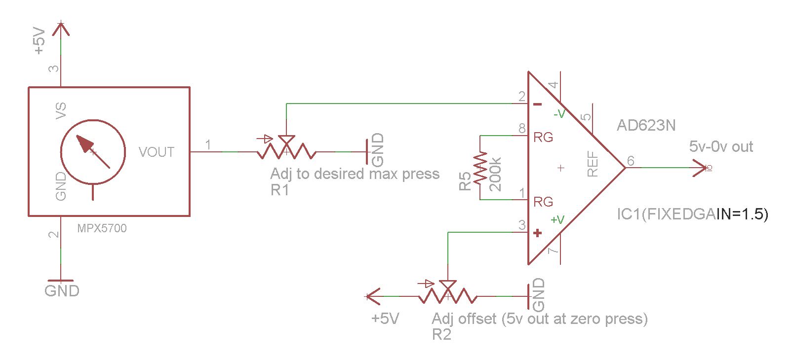
My idea isn't unique, there is an existing commercial hydraulic unit that you can buy, it's expensive though and I like the challenge of DIY ;-) I have a lathe I will be using to build the mechanicals. The commercial design from what I can tell from looking at pictures uses the same MPX5700ASX sensor, and feeds the output into what I beleive is a diferential amplifier circuit similar to this

The opamp they use must be a single supply since there is only 5v and gnd available, and their circuit only has an opamp, 4 resistors and a cap. I'm making an assumption they are amplifying the signal. If not they have designed the cylinder size carefully so it generates 101psi for a "typical" simracers preferred maximum pedal pressure, resulting in the MPX5700 putting out a maximum 4.75v. Either way I don't like that you have a fixed maximum pressure on the pedal to get 100% brakes ingame - I would like to have the advantage of having an adjustable "preferred" maximum pressure so the PC/Game sees a full brake pedal at whatever pressure you choose to dial-in.
I have come up with 2 different possible designs..
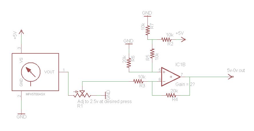
1) use a dual opamp (opamp to be single supply 5v, rail to rail output), use the first opamp in a non-inverting config to amplify the signal to 5v (at the preferred maximum pressure) with a pot to adjust the gain, then feed that into a difference amplifier (gain of 1) to invert the signal so its at the 5v-0v required - so this is my first design

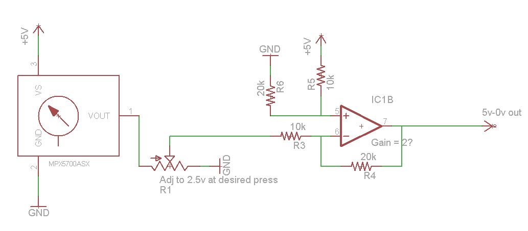
2) use a pot as a simple voltage divider, the pot is adjusted so that the output is 2.5v (at the preferred maximum pressure), then feed that into a difference amplifier with a gain of 2 to invert the singal and bring it back up to 5v so its 5v-0v as required - so this is my 2nd design, its seems simpler but I'm concerned about the difference amplifier being right?

Is either circuit preferred for my application, and have I got them right?
I'm a total hack with electronics, generally I look at how others have done circuits and try to modify them to suit what I need, so be warned I may be missing some fundamentals.
I am building a hydraulic/pnuematic brake system for use with an existing PC steering wheel - I sim race online every week!
I'm waiting for some hardware for my pressure cylinder, but the basics are that when I apply the brake pedal I expect to go from 0psi to around 70-80psi in the cylinder. I plan on using a freescale MPX5700ASX sensor to detect the pressure and the sensor outputs 0-4.7v over 0-101psi
therefore I'm expecting to generate 0v-4v approximately as I use my brake pedal.
My steering wheel uses 5v-0v on the existing pedal so it's inverted and also uses close enough the full 5v range (there's a 5v supply to the pedal unit)
My idea isn't unique, there is an existing commercial hydraulic unit that you can buy, it's expensive though and I like the challenge of DIY ;-) I have a lathe I will be using to build the mechanicals. The commercial design from what I can tell from looking at pictures uses the same MPX5700ASX sensor, and feeds the output into what I beleive is a diferential amplifier circuit similar to this
The opamp they use must be a single supply since there is only 5v and gnd available, and their circuit only has an opamp, 4 resistors and a cap. I'm making an assumption they are amplifying the signal. If not they have designed the cylinder size carefully so it generates 101psi for a "typical" simracers preferred maximum pedal pressure, resulting in the MPX5700 putting out a maximum 4.75v. Either way I don't like that you have a fixed maximum pressure on the pedal to get 100% brakes ingame - I would like to have the advantage of having an adjustable "preferred" maximum pressure so the PC/Game sees a full brake pedal at whatever pressure you choose to dial-in.
I have come up with 2 different possible designs..
1) use a dual opamp (opamp to be single supply 5v, rail to rail output), use the first opamp in a non-inverting config to amplify the signal to 5v (at the preferred maximum pressure) with a pot to adjust the gain, then feed that into a difference amplifier (gain of 1) to invert the signal so its at the 5v-0v required - so this is my first design
2) use a pot as a simple voltage divider, the pot is adjusted so that the output is 2.5v (at the preferred maximum pressure), then feed that into a difference amplifier with a gain of 2 to invert the singal and bring it back up to 5v so its 5v-0v as required - so this is my 2nd design, its seems simpler but I'm concerned about the difference amplifier being right?
Is either circuit preferred for my application, and have I got them right?