Continue to Site

Welcome to EDAboard.com

Welcome to our site! EDAboard.com is an international Electronics Discussion Forum focused on EDA software, circuits, schematics, books, theory, papers, asic, pld, 8051, DSP, Network, RF, Analog Design, PCB, Service Manuals... and a whole lot more! To participate you need to register. Registration is free. Click here to register now.

How to simulate an equiangular spiral antenna in HFSS

Status
Not open for further replies.

nodoubt

Newbie level 4
Newbie level 4
Joined
Nov 5, 2010
Messages
7
Helped
2
Reputation
4
Reaction score
2
Trophy points
1,283
Activity points
1,355
Hi dear friends,

I am trying to simulate my equiangular spiral antenna in HFSS for my thesis a long time ago, but unfortunately it doesn't work well...

I tested two configurations for the antenna: one with right hand polarisation (RHP) and another with Left hand polarisation (LHP). The results are attached for both polarisations of the antenna.

I also used a lumped port for testing each antenna.

My results are really bad... I don't understand why!

I attached my results and the hfss files.

I would appreciate if you could take a look at my files. Thank you very much for your help.

Here are my files:

View attachment RHP.zip
View attachment LHP.zip
View attachment Spirals_HFSS.zip

Kind regards
 
Last edited:

The lumped port sheet seems somewhat... suboptimal. I would copy the whole structure, intersect it with a centered circle and then connect all the new corners by line elements and finally close the line.

Everything else seems fine - just that the antenna performance is really disappointing... I found that, in traveling wave antennas such as those spiral antennas, the feeding structure is actually really important. Maybe you should try out some more ideas in that area.
 
The lumped port sheet seems somewhat... suboptimal. I would copy the whole structure, intersect it with a centered circle and then connect all the new corners by line elements and finally close the line.

Hi roxxon. Thank you for your reply. Do you mean that the lumped port must be symmetrical when connected to each arm of the spiral? Would you intersect the circle at the origin (right?), and then do it similarly as I did to the lumped port I have drawn? Am I right?

Thank you!
 
  • Like
Reactions: tazari

    tazari

    Points: 2
    Helpful Answer Positive Rating
Yes. I don't think your lumped port was completely unusable, but it should only be connected at two edges and yours touched the spiral on the side as well.

Yes, draw a circle, centered at the origin, so that when you intersect it with your antenna (which you of course copy before intersecting) gives you four corners, on which you can nicely draw a rectangle by just using the straight line tool and closing the line.

Dear roxxon,

Can you help me please about drawing that correctly? I already tried a thousand times to fix it, but I can't do it correctly! I would really appreciate your help, once I have to submit my thesis very soon, and no one in my faculty can help me at the moment with it...

Thank you very much.
 
Okay, here's the fixed version of your RHP spiral - I only fixed the port, the total performance remained unfavorable. I don't think, it is so easy as just to subtract the normal log spiral from a rectangle and use it again as broadband antenna... otherwise, there would not be a Babinet's Principle. :)
 

Attachments

  • spiral - RHP.zip
    120.9 KB · Views: 295
Okay, here's the fixed version of your RHP spiral - I only fixed the port, the total performance remained unfavorable. I don't think, it is so easy as just to subtract the normal log spiral from a rectangle and use it again as broadband antenna... otherwise, there would not be a Babinet's Principle. :)

Oh, thank you a lot roxxon! I really appreciated your help. Yes, you are right about that. Well, the strange thing is that the antenna in the real case works fine. The PCB is exactly the same model. I think the problem should be on the lamped port though. Do you think that with a wave port, it would
have a different behaviour?
 

Hmm... how did you feed it then, in the real case? And is the PCB thickness and material the same? How about the measurement environment - was the antenna really measured without any ground?

I think, there has to be a dominant discrepancy between your HFSS model an the real case... For example, I found that, when I build the test antenna with an SMA connector, I also have to include that in the model, at least in the last step.

Well, in fact I forgot to mention that... the fed is made with a coaxial cable fixed on the spiral arms of copper (as an infinite balun. I also have put a dummy cable. In HFSS model the orange is the copper as you know), which I can't draw in HFSS. The thickness is a bit larger, but I suppose it doesn't have influence. The material I used to print the PCB is FR4, which is different than the rogers used in HFSS... but I suppose FR4 has more losses. Ah, and I am measuring the antenna testing it with another ground plane in the backs to act like a reflector (to radiate only one side of course) and without reflector. Although, I will use the ground plane in the end of course.

Well, I am also using a SMA connector to connect it to VNA of course. How do you include it in HFSS model? Thank you.
 
Last edited:

So, there are quite a few differences between the model and the reality...

- How far away is the ground in practice? Generally, ground planes have a huge impact on the overall impedance and efficiency (since then generally most of the electric field is in between the antenna structure and the ground plane).

- If you use FR4 in practice, there really is no reason why you would use Rogers in HFSS.

- You can always use a SMA connector model to feed your antenna, if that's what you do in practice (I didn't quite get that from your description): draw two cylinders, one being the inner conductor with a radius of typically 0.65mm (1.3mm diameter is used by most SMA connectors like H&S, etc., but use the one you actually have, of course) and the outer cylinder with radius rInner*exp(5/6*sqrt(eps)) where eps is the relative permittivity of the isolation material of your connector (usually Teflon, eps=2.1). The inner cylinder of course should be PEC or copper, while the outer is made of the isolation material (Teflon). Subtract the inner from the outer (check the copying box). At one end the inner conductor should reach out to the structure you want to feed and at the other you apply a full solid PEC cylinder of the same radius as your isolation cylinder, with a thickness of, lets say 1mm. The whole connector sould be 3-5mm long. Press the "F" on the keyboard and mark the lateral surface of the isolation cylinder and apply PerfE boundary. Mark the inner top surface of the PEC end cylinder (or the adjoint surface of the isolation cylinder, with a whole in the middle) and apply a waveport excitation with the integral line reaching from the inner straight to the outer radius. You can use the deembed-function and deembed the whole connector length (the 3-5mm), to get zero phase offset.

I use the coax connector most of the time and got very good agreement with practice in general.

dear roxxon,

can you please do me that? I have to submit my thesis in some hours and I still don't have good results. Thank you...
 

Do what? As you can imagine, I actually have to work and most certainly can not / won't do the work for you!
 

Do what? As you can imagine, I actually have to work and most certainly can not / won't do the work for you!

Dear roxxon,

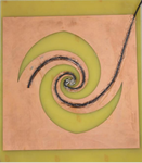
I am sorry about asking you that...I didn't mean you to make me that. Actually, the last days were kind of hard days, so I was with lots of work in hands, and I got a bit unorganised. About the SMA conductor you've suggested, I will show you what I made in practice (see the image attached please).

Sem Título.png

Actually, I have 2 PCB. The one I show you in the image I attached has the coaxial cable intact. I glued a coaxial cable to the copper in one arm and I put a SMA connector in one end to connect it to VNA. At the origin I connect it to the other arm. To give simmetry I glued a dummy cable on the other arm, as you can see.
On the other PCB I have the same scheme, but this time I have cut the outter plastic of the coaxial cable and I soldered the coaxial cable (the mesh) to the copper. I made the same proceedment as to the other PCB as I've wrote.
Taking this into account, do you still suggest a SMA connector to HFSS like you've said? Thank you very much.
 

Sir i am simulating 4 arm microstrip spiral antenna ..can u please look at my problem i am not able to get results like good gain , good RHCP ..I think even my antenna is not at all radiating ..what dimensions of rad box i shud look fr ...i would be grateful to you i am attaching file hereby..
 

Attachments

  • 4Arm_1.rar
    24 KB · Views: 176
Well, I opened your file and found several mistakes:
- you did not apply radiation boundary on the RadBox
- you did not apply PerfE to the coax lateral surfaces
- there was some error concerning bad geometry on the FiniteGND surface, I redid it by pressing F, selecting the surface and "Edit->Surface->Create object from face" (after which you still have to cut out the coax again, of course)

Then it went just fine.
 

Sir can u pls send me the corrected file ..i would be thankful to u ...also sir can u pls help me with the radaition box dimensions...

Thank u so much

---------- Post added at 09:08 ---------- Previous post was at 08:09 ----------

Sir please send me the corrected file as soon as possible as my work is all stuck nd i am nt able to proceed with ..i would be highly grateful to u ..Thanks
 

So... I also found that the diameters of the coax stubs were not 50Ohms - maybe by choice? I changed it to 50 Ohms and applied an octagon approximation (because my PC has only 8GB of RAM and the center appeared to take up a lot of triangles...)

Also, I applied some mesh restrictions; with them I got a nice convergence after 7...8 adaptive passes. But, since you wanted the file right away, I did not have any time to actually check the solutions... So, have fun :)
 

Attachments

  • 4Arm_2.zip
    32.7 KB · Views: 190
Sir,

I am very thankful to you for your effort nd time ..it would be grateful if you still look at the file and check out the results for once ..I will also start simulating it ..Sir it seems to be that u hav a gr8 knowledge in this software ...I am fan of you now ..thanks man ...

Sir please look at the simulations and mail me the new one if it simulates good ..waiting for your reply ..

Can i get your mail id for ny further help nd correspondence ..Thanks a lot ..
 

Sir,

It has no good gain ..wht i can change to achieve good gain ? Cross pol as well as RHCP is low..PLease suggest me ...

Thanks
 

Well... what did you expect..? ;-)

I did not get, how the whole antenna should work in the end. There are four arms -- will all of them be connected to actual signals, e.g. with 90 degrees delay between?

After the first simulation, only one arm is excited. You can adjust the excitations from the menu "HFSS -> Fields -> Edit Sources..." . Right after the first simulation only Port 1 has power applied, all others are "off". To turn them on, adjust the scaling factors and maybe (depending on what the working principle of your antenna should be) also adjust the offset phases. Note, all those adjustments are done after the solving process, so you can play around a bit.
 
Status
Not open for further replies.

Part and Inventory Search

Welcome to EDABoard.com

Sponsor

Back
Top