thuhtay
Newbie level 6

hi Mr.Taner and all of friends
I would like to discuss some issues in his inverter design. This design is so interest. I also tested and constructed it. The output is fine results. But, at the output voltage's amplitude is around 170Vac, Pure sine wave form is stable. In order to get the 200 Vac we adjust the gain of the voltage sensing amplifier. However, it can not handle to the variable load. It is stable at 20 Watts (small load). We would like to handle more load to the desired 550 Watts and more. So Some of the factors and source code Program will be updated. I would like to post of my testing results as well as simulations and experimental test results as attachments in order to discuss and suggest for the improved taner's design. I would like to thanks a lot for all friends in our forum.
all of friends, After downloaded and seen my experimental results, Pls give me valuable suggestions and advices.
with regards
thuhtay
Simulation results
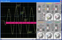
88_1306272200.jpgSimulation Output Waveform of Pure Sine Wave Inverter
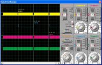
24_1306272200.jpgPeriodic PWM signals and Directional signal
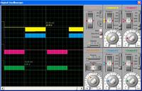
52_1306272200.jpgPWM output signals of the Pre-driver circuitries
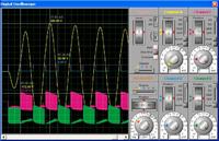
42_1306272200.jpgPWM Output Waveforms of the High Side MOSFETs57_1306272200.jpgPWM Output Waveform of the Low Sided MOSFETs
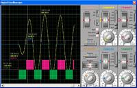
Experimental Test results
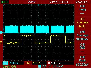
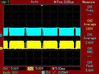
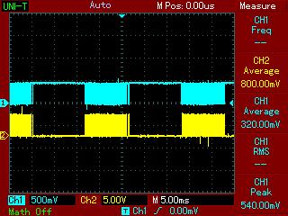
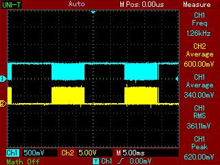
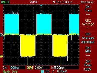
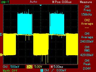
Here, we can see that simulation and experimental results are same as the desired outputs
I would like to discuss some issues in his inverter design. This design is so interest. I also tested and constructed it. The output is fine results. But, at the output voltage's amplitude is around 170Vac, Pure sine wave form is stable. In order to get the 200 Vac we adjust the gain of the voltage sensing amplifier. However, it can not handle to the variable load. It is stable at 20 Watts (small load). We would like to handle more load to the desired 550 Watts and more. So Some of the factors and source code Program will be updated. I would like to post of my testing results as well as simulations and experimental test results as attachments in order to discuss and suggest for the improved taner's design. I would like to thanks a lot for all friends in our forum.
all of friends, After downloaded and seen my experimental results, Pls give me valuable suggestions and advices.
with regards
thuhtay
Simulation results
88_1306272200.jpgSimulation Output Waveform of Pure Sine Wave Inverter
24_1306272200.jpgPeriodic PWM signals and Directional signal
52_1306272200.jpgPWM output signals of the Pre-driver circuitries
42_1306272200.jpgPWM Output Waveforms of the High Side MOSFETs57_1306272200.jpgPWM Output Waveform of the Low Sided MOSFETs


Experimental Test results


Here, we can see that simulation and experimental results are same as the desired outputs
Last edited:


