imuuu_imran
Newbie level 6

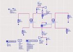
I am trying to build a PIN diode controlled variable gain attenuator by using two branch line directional coupler for my master's thesis at 7.5 GHz. In one journal they made such attenuator from 0dB coupler**broken link removed**. I have to use branch line instead of 0dB coupler. I need a schematic diagram for that with the controlling circuit of the pin diode. I have made a branch line directional coupler in ADS.
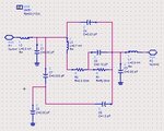
 I have tried to find a s2p file for PIN diode but unable to find one. at the end I found a ADS sub-circuit of the PIN diode Agilent HSMP-3810 in the internet but I don't know it is right or wrong.
 . Also I need to know this sub-circuit is ok or not? Can some one help me?? :sad:
 I have tried to find a s2p file for PIN diode but unable to find one. at the end I found a ADS sub-circuit of the PIN diode Agilent HSMP-3810 in the internet but I don't know it is right or wrong.
 . Also I need to know this sub-circuit is ok or not? Can some one help me?? :sad:


