Continue to Site

Welcome to EDAboard.com

Welcome to our site! EDAboard.com is an international Electronics Discussion Forum focused on EDA software, circuits, schematics, books, theory, papers, asic, pld, 8051, DSP, Network, RF, Analog Design, PCB, Service Manuals... and a whole lot more! To participate you need to register. Registration is free. Click here to register now.

[SOLVED] Voltage regulator beginner question

Status
Not open for further replies.

konnichiwa_ichigo

Newbie level 2
Newbie level 2
Joined
Jun 17, 2011
Messages
2
Helped
0
Reputation
0
Reaction score
0
Trophy points
1,281
Activity points
1,297
I'm totally new to electronics, so forgive me if this is some obviously silly question. I have purchased an XBee adapter which has a 5 to 3.3V voltage regulator for voltage input. Does this mean I can provide voltage anywhere between 3.3 to 5V? Or must I provide a 5V voltage? (e.g. Can I provide a 4.5V voltage tot he adapter with three 1.5V battery?

The data sheet for the XBee adapter can be found here:
**broken link removed**
 

This means you power up the board with 5V. It must be 5V or close to it. There is a voltage regulator on the pcb that outputs 3.3V that is used for your logic signals.
 

The datasheet says 3.3v on-board regulator and 5 V to 3.3 V logic translator buffers, the 5 to 3.3v has to do with the digital input level.
The Power Requirements are 5 VDC I don't think you should use a lower voltage and you may also have problems with the input buffers if you do.

Alex
 
Can you read the part number of the 3 terminal voltage regulator on the pcb? If so you can look up this datasheet and it will tell you the minimum voltage you are able to supply to achieve 3.3V output.
 
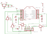
If the schematic is this

xbee-ftdi-board-schematic1.png

then the 74AHC125 buffer is powered with the 3.3v regulated supply so a lower voltage input supply shouldn't be a problem assuming that it is above the minimum input voltage for the regulator to output 3.3v.
In the schematics I found the regulator is shown as LM2937 (maybe yours is different so you have to check), if this is the case then it has a low dropout of 0.5v so you can use the 4.5v.

Alex
 
Thanks to your help, I'm able to complete the first step of my wireless sensor network (at least able to get the data out from sensors to internet, even though the sensor output do not seem correct at the moment). Seems like 4.5V input works! Many thanks! ^_^
 

Status
Not open for further replies.

Similar threads

Part and Inventory Search

Welcome to EDABoard.com

Sponsor

Back
Top