Continue to Site

Welcome to EDAboard.com

Welcome to our site! EDAboard.com is an international Electronics Discussion Forum focused on EDA software, circuits, schematics, books, theory, papers, asic, pld, 8051, DSP, Network, RF, Analog Design, PCB, Service Manuals... and a whole lot more! To participate you need to register. Registration is free. Click here to register now.

[SOLVED] Making a 3 way switch using triac

Status
Not open for further replies.

mamech

Full Member level 3
Full Member level 3
Joined
Nov 9, 2010
Messages
176
Helped
0
Reputation
0
Reaction score
0
Trophy points
1,296
Activity points
3,135
Hello Everyone

I have tried to do action-like 3 way switch using 2 transistors an pnp and an npn.

But I am asking about the simplest way that I can do the same with a triac.

I think I will need 2 triacs to do so.right?


Thanks
 

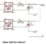
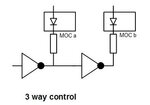
Two triac switch parallel and control as you need.

Triac Sw 01.jpg


Triac Sw 3 way 01.jpg

KAK
 
Last edited:
  • Like
Reactions: mamech

    mamech

    Points: 2
    Helpful Answer Positive Rating
Thank you for your help.

But Can I use MOC3020 or MOC3022 ? I have read that they are non zero crossing, but they are used also to control triacs .What will be different if I used one of them?
 

The differences:

(1)
If your driving circuit doesn't have a zero crossing detector, the starting turn-on of the triac may happen any time during a half cycle (its turn-off will occur automatically when its current return to zero). This could be used when dimming is not required and the minimum load on-off period is many cycles of the main power.

(2)
The non zero crossing version is necessary if the load needs dimming. In this case:
(a) The circuit must know the start of each half cycle.
(b) The triac driving signal should have the same 'phase' delay for every pair of half cycles so that the load average current will be close to zero as possible.
(c) The limiting series resistor (at the MOC output) should be calculated for the worst case; Rs < Vpeak/1A but its average power depends on the response time of the triac at Vpeak.

Edited:
Note: The dissipation of Rs, when MOC is triggered at the zero crossing, is higher for less sensitive triacs (that need high trigger gate current) since the voltage of the output triac should raise more to trigger its base.

Added:
For the zero crossing detector, you may like to read:
https://www.edaboard.com/threads/213123/
 
Last edited:
  • Like
Reactions: mamech

    mamech

    Points: 2
    Helpful Answer Positive Rating
I have bought moc6063, which has zero crossing detector.

I have 2 more questions:

1- For this type , what is the form of microcontroller signal that I must send?
As I understand , I should make the pin connected to the opto coupler to go to zero logic as long as I want the triac to conduct, similar to operation of the relay (but the logic is inverted here)
Is what I am saying right?

2- Can I make dimming for light by making burst control? I mean I make a cycle passes then the second not, so I get the half of light intensity?


Thanks
 

I think you meant MOC3063

Answer (1)
You are right. The MCU pin could be connected to pin 2 of the optocoupler (which is the cathode of the input LED). Then you can add a resistor (Rs) between pin1 of the optocoupler (which is the anode) and Vcc. Please note that it doesn’t matter if (Rs) is connected before or after the input LED. In this case, to turn on the triac of the optocoupler, the MCU pin is made low.

On the datasheet, the typical trigger current is 5mA (I_trg) but if you like you can let it be a bit higher, say 8mA for example. On the other hand, the LED forward voltage (V_led) is about 1.3V. Knowing (I_trg) and (V_ref) and assuming (Vcc=5V), we can calculate (Rs):
Rs = (Vcc – V_led) / I_led
Rs = (5 – 1.3) / 8mA = 0.4625 => 470 Ohm
Note: The saturation voltage of the MCU pin (when low) is assumed close to zero (actually it may be about 100mV).

Answer (2)
“Zero Crossing Triac Driver Output Optocoupler” as MOC3063 is not suitable for dimming the light of a bulb. But it may be used to turn on/off a heater to regulate the temperature for example. Fine dimming needs a “Random Phase Triac Driver Output Optocoupler” as MOC3052.
It is better to remember when driving AC loads to fire both halve cycles (consecutive) so that the average current in the load will be always very close to zero. So your suggestion to pass one full cycle and block the following one to get half power is right electrically. But the produced light in this case would have a frequency of 25 Hz which is not comfortable to our eyes (normally it is 100 Hz since the light power is always positive for all half cycles).

In general, the zero cross type is easier to work with, since the trigger always occurs at a low mains voltage which lets the dissipation of the output current limiting resistor (in series with the gate of the power triac and the optocoupler output) be minimal. On the other hand, the MCU doesn’t need to be triggered by a zero cross detector. The price is that the on/off periods should be made rather slow (the minimum is 20ms for 50 Hz).

The random type is used to control the power at the same frequency of the AC source. But the driving circuit at the optocoupler output has to be designed carefully. The power device for the load could be a triac (one gate) or a bi-thyristor with two separate gates. In both cases one should consider the possible difference in the gate sensitivity (trigger current) when the phase delay is very small. The on-time of a half cycle would be different from the following one (since the voltage on the power device should rise till its gate current is high enough to trigger it). The remedy is to choose a minimum phase angle (to start with for the highest power) at which the voltage on power device is high enough to trigger it in both half cycles without extra delay in either one. Here, the dissipation of the output current limiting resistor is higher than for the zero cross type. Its worst case is at 90 deg trigger phase. Also the MCU needs an external interrupt to follow the timing of the mains voltage zero crossing.


As a first step, perhaps it is better to work with MOC3063.
Please take care when a part of your circuit is connected to a high voltage.
I hope your AC voltage is provided by an insulating (220V/220V for example) transformer so if you touch one of its two (secondary) terminals it becomes as ground.
 
  • Like
Reactions: mamech

    mamech

    Points: 2
    Helpful Answer Positive Rating
Status
Not open for further replies.

Similar threads

Part and Inventory Search

Welcome to EDABoard.com

Sponsor

Back
Top