speedEC
Full Member level 6

Increase Amps in 6v, 4.2Ah Battery Charge circuit
Dear All,
I need three clarifications and also need help to sort out the issues related to 6v, 4.2Ah Lead Acid Battery charging.
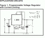
I have designed battery charging circuit based on "L200" IC as shown here.

R1 - 820 ohms
R2 - 4.7k (fixed) resistor
R3 - 0.5 ohms /5 W resistor
Also to prevent battery discharge I have used 1N4007 diode in between the output of the Circuit and Battery.
Battery's voltage : 6.73v
The output current of the circuit is around 100mA (If I used Diode).
The output current of the circuit is around 230mA (without Diode).
But, if I constantly measure the current output on the circuit using multimeter, it gradually decreases. Why?
Clarification 1:
1. If the battery (while charging) voltage increase, will the current decrease?
The current output formula:
R3 (in Ohms) = 0.45 / Imax (in amps)
so, if I used 0.5(R3) ohms, then Imax = 0.45/0.5 = 0.9 amps should be drawn from the circuit. Am I right?
I need to show the LED (GREEN) when the battery becomes fully charged and disconnect the battery charging even if the battery connected to the circuit. Also need to show the LED (RED) if the battery charge is low. How can I do that? Is there any possibility to use this same circuit to do that or should I use separate voltage monitor circuit. Of course, I already made "low voltage monitor circuit" using uA741 IC. It works fine.
Clarification 2:
Should I use separate circuits for low and high voltage indicators and disconnect the charger if battery fully charged?
I have to power-up the PIC (1.8 - 5.5v), 5v Relay and one Buzzer (3 - 12v) using this 6v, 4.2Ah Battery. Some of our friends here, advised me to use two diodes in series to reduce the voltage from 6v to 5v(near). I did that too and I am getting 5.25v fine. I have connected 5.6v zener diode in series. But, some one recommends to use the diode with resistor component (diode-resistor combination) for safety.
Clarification 3:
I like to know which value of the resistor should be used?
These are the clarifications I required. Sorry for the lengthy thread. I am in the final stage of the project.
Pl help me.
Advance thanks
Dear All,
I need three clarifications and also need help to sort out the issues related to 6v, 4.2Ah Lead Acid Battery charging.
I have designed battery charging circuit based on "L200" IC as shown here.

R1 - 820 ohms
R2 - 4.7k (fixed) resistor
R3 - 0.5 ohms /5 W resistor
Also to prevent battery discharge I have used 1N4007 diode in between the output of the Circuit and Battery.
Battery's voltage : 6.73v
The output current of the circuit is around 100mA (If I used Diode).
The output current of the circuit is around 230mA (without Diode).
But, if I constantly measure the current output on the circuit using multimeter, it gradually decreases. Why?
Clarification 1:
1. If the battery (while charging) voltage increase, will the current decrease?
The current output formula:
R3 (in Ohms) = 0.45 / Imax (in amps)
so, if I used 0.5(R3) ohms, then Imax = 0.45/0.5 = 0.9 amps should be drawn from the circuit. Am I right?
I need to show the LED (GREEN) when the battery becomes fully charged and disconnect the battery charging even if the battery connected to the circuit. Also need to show the LED (RED) if the battery charge is low. How can I do that? Is there any possibility to use this same circuit to do that or should I use separate voltage monitor circuit. Of course, I already made "low voltage monitor circuit" using uA741 IC. It works fine.
Clarification 2:
Should I use separate circuits for low and high voltage indicators and disconnect the charger if battery fully charged?
I have to power-up the PIC (1.8 - 5.5v), 5v Relay and one Buzzer (3 - 12v) using this 6v, 4.2Ah Battery. Some of our friends here, advised me to use two diodes in series to reduce the voltage from 6v to 5v(near). I did that too and I am getting 5.25v fine. I have connected 5.6v zener diode in series. But, some one recommends to use the diode with resistor component (diode-resistor combination) for safety.
Clarification 3:
I like to know which value of the resistor should be used?
These are the clarifications I required. Sorry for the lengthy thread. I am in the final stage of the project.
Pl help me.
Advance thanks
Last edited:
