Continue to Site

Welcome to EDAboard.com

Welcome to our site! EDAboard.com is an international Electronics Discussion Forum focused on EDA software, circuits, schematics, books, theory, papers, asic, pld, 8051, DSP, Network, RF, Analog Design, PCB, Service Manuals... and a whole lot more! To participate you need to register. Registration is free. Click here to register now.

Sine wave Power output stage

Status
Not open for further replies.

koolchiq

Newbie level 4
Newbie level 4
Joined
Mar 26, 2011
Messages
7
Helped
1
Reputation
2
Reaction score
1
Trophy points
1,283
Activity points
1,338
Can someone help me with a working circuit for my problem. i want to design and implement the output stage of an inverter. I used discrete components for the PWM stage. I am getting 20 v p-p from my LM319 comparator (50Hz sine wave and triangular wave IN). My problem is how do i implement the output stage from here. i have 2 buz11 mosfets and 1 TIP 2955/3055 complimentary pair BJT's. Output not to exceed 30v ac and 1 amp @ 50 Hz. Can i use the BJT's to drive the mosfets or vice-versa? If so ho do i configure the circuit? Please help.

Thank you.
 

Hello koolchiq
Are you going to use this 30v AC 1amp to drive a ac motor or something else? or you want to built 50hz inverter?
 

i can help you koolchiq,but i will like to know you carrier freq and how you modulate the ref singnal and the carrier freq,you can upload your diagram if posible.
 
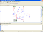
Thank you for your responses. I want to build a 50Hz sine wave inverter. I have attached the output section from the comparator. I used 741( available to me) for the triangular carrier wave but unfortunately am only getting 8KHz, no matter what.I am also getting about 20v p-p. But the big problem now is the final output with voltage and current to drive a resistive load. Thank you very much, you help is much appreciated. I tried TL082 for the carrier wave but they did not work on simulation.
 

Attachments

  • output 1b.PNG
    output 1b.PNG
    51.3 KB · Views: 136
Could you attach the desirable and observed waveforms ?

+++
 

Kabiru, did you manage to have a look at my design problem area i posted? Thanks.
 

Sorry i busy that why i did'nt reply to you in time,i saw your diagram and the simple way to achive it is to generate square wave using op-amp and pass the square wave through an op-amp intergrator then you have your triangular wave but here is another one.
 
I have a sine wave at 50Hz and a triangular signal at 10KHz going into a comparator, then a PWM signal coming out. What i want is to drive either BJT's or Mosfets, filter the signal and reconstruct the sine wave. My problem is designing the power output stage, i.e the driver and configuration for the BJT's/Mosfets to be able to drive a resistive load. I am looking at using BJT's to drive the Mosfets (or vice-versa). I am stuck and really need help on this one.

Thanks.
 

ok now i understand then try this one
 
Thanks Kabiru. But i have said i already have a PWM signal from a comparator and want to use the BJTs i have to drive 2 Mosfets. Thanks.
 

can you simply post your circute diagram let me see were you are stuck so that i can help or are you trying to produce two output from the pwm signal which is out of phase with the other?
 
The output stage is shown in post #4, but it's completely screwed up.
 
what i am seing here is a function generator and op-amp in multism i dont think he desinge the circute he is talking about.
 
Where have i screwed up FvM? That is why i am seeking assistance. Can you help?
Thanks.
 

I noticed:
- LM339 misses a pullp-up resistor
- the BJT driver most likely doesn't switch correctly
- both MOSFET are connected with S and D reversed.
- the MOSFET don't have sufficient current rating for a real circuit
- the complementary MOSFETs are connected as source followers. So they don't turn on completely, the output voltage is considerably below +/-12 V and losses are high

If you ask the other way round: Anything correct with the circuit? As a first step, you possibly should delete the schematic and start a new one from the scratch. Or copying a known working design.
 

Status
Not open for further replies.

Similar threads

Part and Inventory Search

Welcome to EDABoard.com

Sponsor

Back
Top