dumdum123
Newbie level 3

Hello!
Could anyone push me to the right direction with a following design?
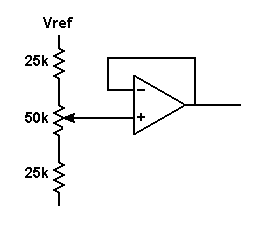
I need to build an voltage source that has an output by conrollable percentage from a variable reference voltage.
I need to control the voltage source with a CPU (with PWM, DC voltage or external DAC), potentiometers are not the solution for controlling, except digital pots.
For example:
Vout = x * Vref
Vref constantly varies somewhere between 12 -14V (voltage from car battery with alternator on/off)
x = 0.25 to 0.75
I've simulated many kinds of op-amp diagrams and such with no solution.
The changing Vref is the problem, gain changes with it and suddenly 0.5*Vref isn't 0.5*Vref anymore...
(I'm not sure if there is an simple op-amp design for this kind of situation)
Could I use MCU+DAC to easily implement this kind of voltage source?
One solution I thought was to 'read Vref with ADC - process MCU - Output an correct voltage with DAC and buffer the output with OP-AMP' This seemed unnecessary complex...
I'm more familiar with digital bus systems/protocols and programming, but analog electronics is quite new to me.
Thanks for any advice!
Last edited:


