Continue to Site

Welcome to EDAboard.com

Welcome to our site! EDAboard.com is an international Electronics Discussion Forum focused on EDA software, circuits, schematics, books, theory, papers, asic, pld, 8051, DSP, Network, RF, Analog Design, PCB, Service Manuals... and a whole lot more! To participate you need to register. Registration is free. Click here to register now.

Circuit Pic16f877 / thermocouple K / ad623 problem

Status
Not open for further replies.
I write the following program (in mikroC pro) and get exactly 508 from AD conversion:
//////////////////////////////////////////////////////////////////////////
//Fosc = 4Mhz, OSC = XT, WDT = Disable //
//////////////////////////////////////////////////////////////////////////
void main()
{
TRISC=0x00; //PORTC output
TRISB=0xF0; //Low nibble of PORTB output
TRISA=0xFF; //All PORTA pins as input
ADCON1=0x80; //Right justified, all analog pins as analog input
ADCON0=0xC1; //RC osc, AD on
while(1)
{
Delay_us(50); //Delay for aquation
ADCON0.B2=1; //Setting Go/Done bit (start AD conversion)
while(ADCON0.B2) //Do nothing until conversion complete
asm nop;
PORTC=ADRESL; //Low byte of result
PORTB=ADRESH; //High byte of result
}
}
/////////////
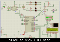
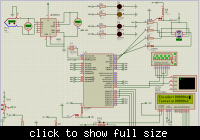
You can see the result as follow:
 

Attachments

  • 2.JPG
    2.JPG
    74.3 KB · Views: 151
The low byte of result inserted to PORTC and the high byte inserted to PORTB. the result is 508.
 
this is really helping me! thank you so much and sorry for your loss of time making the circuit and the code.

so there is no way to increase the range of the thermocouple from 508 to 1250 for example?

i have done the exact same circuit i finaly starting to understand what is happening on the circuit ^^

---------- Post added at 10:37 ---------- Previous post was at 10:16 ----------

I connected the circuit you made into the PIC and it seems that it occurs some voltage loss somewhere!

i connected it to the ground just like you did here


and to the pic in this one


it goes from 2.48 to 1.24 exactly half!
 

Wow!
In the first schematic you connected the voltmeter in series with AN0!
The voltmeter have about 100M ohm impedance and so it drops a large voltage across it.
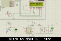
Connect the output of AD595 like this (Voltmeter must be in parallel with AN0):
 

Attachments

  • 3.JPG
    3.JPG
    76.3 KB · Views: 132
hehe :D

noticed that after a while :p i fixed that


i am not the greatest elect guy ever that´s for sure...
 

did you measure correct voltage?

not exactly! but i got the maximum of 500C up to 1000C+-, i need to see what more i have wrong on the circuit!

i pumped the circuit by getting a resistor and a diode on it.


Great work zwilorg!

---------- Post added at 06:22 ---------- Previous post was at 06:18 ----------

I think that you use D5 for protection, but it's not needed. because each of analog pin have two clamping diodes that clamp any voltage above Vdd to about Vdd+0.3, and any voltage below Vss to about Vss-0.3.

---------- Post added at 06:26 ---------- Previous post was at 06:22 ----------

Also i think that you used C1 for stabling. but it's value is very large and can slow down measuring response. decrease it to less than 1uf (or even less than 0.1uf).

---------- Post added at 06:34 ---------- Previous post was at 06:26 ----------

You should decrease R11 to less than 2.5K (while keeping the ratio of R11 to R12 constant, for correct voltage dividing). it should be decreased to measuring more accurate values (for more information see "Analog to Digital converter" section of datasheet of your microcontroller).

---------- Post added at 06:42 ---------- Previous post was at 06:34 ----------

If you want to measure hot junction temperature with less errors:
-->Use 1% (or less) resistor for R11 and R12.
-->Use an external voltage reference for your AD converter (such as LM336-5)
-->Follow the recommendation in AD595 app notes.


Thanks for all the help! i have been searching alot and came up with that built! it is almost there!

i can´t get on it right now but in a few hours i will follow your advices!
 

So in the end i just got it stuck right has the last version! the fidelity of the temperature is not 100% at high temperatures, but with a few changes in the code it goes from bad to acceptable ^^

i will still try those changes you mencioned! thanks for the help hamed8419215!

i will tell you if changing the resistors and capacitor helps the results!
 

Status
Not open for further replies.

Similar threads

Part and Inventory Search

Welcome to EDABoard.com

Sponsor

Back
Top