Continue to Site

Welcome to EDAboard.com

Welcome to our site! EDAboard.com is an international Electronics Discussion Forum focused on EDA software, circuits, schematics, books, theory, papers, asic, pld, 8051, DSP, Network, RF, Analog Design, PCB, Service Manuals... and a whole lot more! To participate you need to register. Registration is free. Click here to register now.

Problem with implementing a digital clock for LCD on breadboard

Status
Not open for further replies.

Fantascy

Junior Member level 1
Joined
Nov 27, 2009
Messages
19
Helped
0
Reputation
0
Reaction score
0
Trophy points
1,281
Visit site
Activity points
1,457
I am designing a digital clock using 89s52 and lcd. My simulation on proteus is working perfectly, now i try to implement it on breadboard but the lcd is not giving me any response, i have double checked my connection. This is my first implemention of a circuit using lcd, what am i not doing well?
 

Re: No response from lcd

LCD initialization may not be perfect....This may be the reason.
try this steps for initialization in 4 bit mode. I also faced same problem. I made many modifications in my program and finally i works..

This is a part of my final code related to LCD in 4 bit mode.


/////////////////////////////////////////////////////////////////
void LCD_STROBE(void)
{
EN = 1;
__delay_us(0.5);
EN = 0;
}
///////////////////////////////////////////////////////////////////
void data(unsigned char c)
{ RS=1;
__delay_us(40);

PORTB = ( c >> 4 );LCD_STROBE();
PORTB = ( c );LCD_STROBE();

}
///////////////////////////////////////////////////////////////////
void cmd(unsigned char c)
{ RS=0;
__delay_us(50);

PORTB = ( c >> 4 );LCD_STROBE();
__delay_us(5);
PORTB = ( c );LCD_STROBE();
__delay_us(5);
}
//////////////////////////////////////////////////////////////////
void clear(void)
{

cmd(0x1);
__delay_ms(2);
}
//////////////////////////////////////////////////////////////////
void lcd_init()
{__delay_ms(20);
cmd(0x30);
__delay_ms(20);
cmd(0x03);
__delay_us(200);
cmd(0x03);
__delay_us(200);
cmd(0x03);

cmd(0x28 ); // Function set (4-bit interface, 2 lines, 5*7 Pixels)
cmd(0x0c); // Make cursor invisible
clear(); // Clear screen
cmd(0x06); // Set entry Mode
}
 

Re: No response from lcd

;this is my code

org 00h
ljmp main
org 003h
ljmp rest
org 0013h
ljmp est

main: call initialize_lcd
mov ie,#85h ;configuring interrupt 0 and 1.
setb tcon.0 ;enabling interrupt 0. Used to set the minutes
setb tcon.2 ;enabling interrupt 1. Used to set the hour.

mov tmod,#11h
aa: mov 31h,#2
mov r5,#30h
call display_hr2
bb: mov r4,#30h
call display_hr1
cc: mov r3,#30h
call display_min2
dd: mov r2,#30h
call display_min1
ee: mov r1,#30h
call display_sec2
ff: mov r0,#30h
xx: call display_sec1
call one_sec_delay
inc r0
cjne r0,#3Ah,xx
inc r1
call display_sec2
cjne r1,#35h,ff
inc r2
call display_min1
cjne r2,#39h,ee
inc r3
call display_min2
cjne r3,#35h,dd
djnz 31h,set_hr_limit
set_hr_limit: inc r4
call display_hr1
cjne r4,#39h,cc
inc r5
call display_hr2
cjne r5,#32h,bb
ret

inc r4
call display_hr1
cjne r4,#33h,cc
jmp aa

initialize_lcd: mov a,#01h
call command_inst
mov a,#06h
call command_inst
mov a,#0ch
call command_inst
mov a,#10h
call command_inst
mov a,#84h
call command_inst
mov a,#':'
call data_inst
mov a,#89h
call command_inst
mov a,#':'
call data_inst
ret

command_inst: mov p1,a
clr p2.0
clr p2.1
setb p2.2
clr p2.2
call delay_lcd_10milisec
ret

data_inst: mov p1,a
setb p2.0;rs
clr p2.1;r/w
setb p2.2;en
clr p2.2
call delay_lcd_10milisec
ret

delay_lcd_10milisec: mov th0,#0d8h
mov tl0,#0f0h
setb tr0
yy:jnb tf0,yy
clr tf0
clr tr0
ret

one_sec_delay: mov 30h,#20
load: mov th1,#3ch
mov tl1,#0b0h
setb tr1
zz: jnb tf1,zz
clr tr1
clr tf1
djnz 30h,load
ret

display_sec1: mov a,#8ch
call command_inst
mov a,r0
call data_inst
ret


display_sec2: mov a,#8bh
call command_inst
mov a,r1
call data_inst
ret


display_min1: mov a,#87h
call command_inst
mov a,r2
call data_inst
ret

display_min2: mov a,#86h
call command_inst
mov a,r3
call data_inst
ret
display_hr1: mov a,#82h
call command_inst
mov a,r4
call data_inst
ret

display_hr2: mov a,#81h
call command_inst
mov a,r5
call data_inst
ret

rest: inc r2
mov a,#87h
call command_inst
mov a,r2
call data_inst
reti

est: inc r4
mov a,#82h
call command_inst
mov a,r4
call data_inst
reti

end


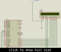
this is the circuit diagram


pls what i need to know about lcd contrast and vEE in lcd pins
 

contrast pin should be connected to a potentiometer.. one end to +5V other end to ground and middle pin to Port pin and contrast pin ... dont forget to use pull up resistor for all port pins of 10K....

unable to open the circuit... pin 1 and 16 gnd and pin 2 and 15 to vcc
 

I am designing a digital clock using 89s52 and lcd. My simulation on proteus is working perfectly, now i try to implement it on breadboard but the lcd is not giving me any response, i have double checked my connection. This is my first implemention of a circuit using lcd, what am i not doing well?

Ok...ur ciruit works perfectly on Proteus then it means that there is no issue with the code[Stage one completed:)].
There can be few chances due to which ur LCD isn't working:
1. The Pin Configuration which u defined in the Code is by mistake not being used by u.
2. Check the sequence of the pin numbers(LCD). Might possible u have inserted wires in reverse order i-e u would have inserted Data Pins wires in Rs/RW/E/Vcc etc pins and vice versa.So i recommend u better check the pin sequence.
3. Might possible that you haven't provided the required Vcc or Vcc .
4. Last but no the least check ur LCD. Might possible its faulty from inside or its Vcc pin or RW pin are faulty ones.
 

contrast pin should be connected to a potentiometer.. one end to +5V other end to ground and middle pin to Port pin and contrast pin ... dont forget to use pull up resistor for all port pins of 10K....

unable to open the circuit... pin 1 and 16 gnd and pin 2 and 15 to vcc
i dont understand what you mean by pin 1 and 16 and pin 2 and 15. my lcd has a total of 14 pins.

---------- Post added at 23:51 ---------- Previous post was at 23:46 ----------

click here to view the circuit diagram
 

some lcd have 16 pins and some have 14 pins. if it is 14 pins then 16 is internally shorted to 1 and 15 is shorted to 2.. dont worry about that.....

In proteus it will work .. but in practical life as i told you have to connect a pull up resistor of 10k resistor to each port pin.. when you use potentiometer to pin 3 of lcd and tune it then you should see black box appear on lcd.
 
My friend
If your design working at the PROTEUS then there is no problem for the code but the problem at the hardware itself double check the folowing

1- your crystal osc because it will Chang the timing
2- your hardware connection
3- LCD contrast pin pin 3

Best Regards

MedTronic
 
Status
Not open for further replies.

Similar threads

Part and Inventory Search

Welcome to EDABoard.com

Sponsor

Back
Top