Continue to Site

Welcome to EDAboard.com

Welcome to our site! EDAboard.com is an international Electronics Discussion Forum focused on EDA software, circuits, schematics, books, theory, papers, asic, pld, 8051, DSP, Network, RF, Analog Design, PCB, Service Manuals... and a whole lot more! To participate you need to register. Registration is free. Click here to register now.

help me please, i'm trying to design a vivaldi antenna

Status
Not open for further replies.

elenafuentes

Newbie level 4
Newbie level 4
Joined
Feb 7, 2011
Messages
7
Helped
0
Reputation
0
Reaction score
0
Trophy points
1,281
Activity points
1,332
hi everybody i'm a beginner in this things, i'm should to design a vivaldi antenna in HFSS v12, but honestly I'm a little frustrated because not found a tutorial that really help me and explain me step by step how to design this antenna.

please need your help, i will thank you so much.

Thanks, i will your answer, and sorry for my english :sad:
 

hi again, also i dont know how can i use the lumped port and the wave port? what is the difference between them? thanks a lot =).


sorry for my english again

---------- Post added at 20:17 ---------- Previous post was at 20:16 ----------

hi again, also i dont know how can i use the lumped port and the wave port? what is the difference between them? thanks a lot =).


sorry for my english again
 

hi
which kind of vivaldi u want to design ? what BW u want?
 
Hi elenafuentes,
You should install the Antenna Design Kit from Ansoft Website. This is a good starting point.
You can find answers in this forum regarding the difference between lumped and waveports or in the HFSS help ... but here again:
Lumped ports:
Lumped ports are similar to traditional wave ports, but can be located internally and have a complex user-defined impedance. Lumped ports compute S-parameters directly at the port.The complex impedance Zs defined for a lumped port serves as the reference impedance of the S-matrix on the lumped port. The impedance Zs has the characteristics of a wave impedance; it is used to determine the strength of a source, such as the modal voltage V and modal current I, through complex power normalization. (The magnitude of the complex power is normalized to 1.) In either case, you would get an identical S-matrix by solving a problem using a complex impedance for a lumped Zs or renormalizing an existing solution to the same complex impedance.
By default, the interface between all 3D objects and the background is a perfect E boundary through which no energy may enter or exit. Wave ports are typically placed on this interface to provide a window that couples the model device to the external world.

Wave ports:
HFSS assumes that each wave port you define is connected to a semi-infinitely long waveguide that has the same cross-section and material properties as the port. When solving for the S-parameters, HFSS assumes that the structure is excited by the natural field patterns (modes) associated with these cross-sections. The 2D field solutions generated for each wave port serve as boundary conditions at those ports for the 3D problem. The final field solution computed must match the 2D field pattern at each port.
HFSS generates a solution by exciting each wave port individually. Each mode incident on a port contains one watt of time-averaged power. Port 1 is excited by a signal of one watt, and the other ports are set to zero watt. After a solution is generated, port 2 is set to one watt, and the other ports to zero watt and so forth.
 
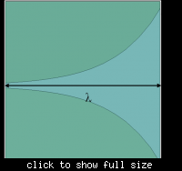
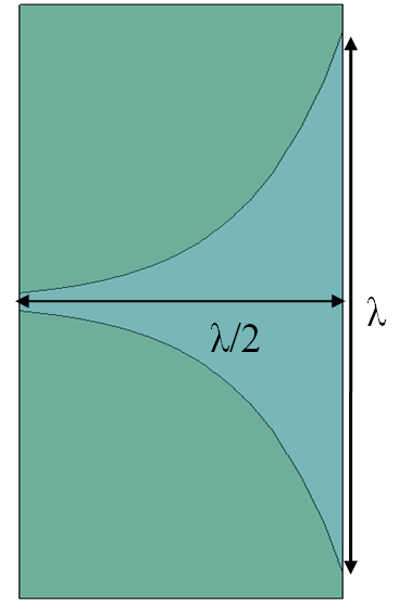
For the vivaldi antenna, at what frequency are you planning to design? On which substrate are you planning to fabricate. I simulated different vivaldi antennas in HFSS. You can see the attached figures (exponential tapers). But in order to fabricate the vivaldi antenna and test it, you will need a microstrip to slotline transition.

-sv

91_1302151928.png
 
Last edited:
Hi
hfss antenna design kit can help amateur to design antenna but the antenna design with it not very good
 
thank you so much for the help =) and sorry for dont give you all the information (i was concerned).

well, according to my professor the antenna should work from 1 to 5 GHz approximately. My first question: is good this BW??

i have read papers about this antennas, first i was thinking in design a Tapered Slot Antenna that is the most common, but later i read that is better the Antipodal Vivaldi antena and the balanced antipodal vivaldi antenna.

- What is the type of antenna more appropriate for design? (remember that i am a begginer)

-about the substrate, the fr4 its ok? or what type of substrate you recommend me?

-i have the hfss antena design kit but i feel that is not very good, for the type of antenna that i want to design

thanks again and sorry for my english =)
 

Generally, I don't prefer FR4 for frequencies greater than 2 GHz. Vivaldi antennas are pretty broadband antennas and you can easily achieve the BW of 1 to 5 GHz using Vivaldi antennas.

For high frequencies, I suggest Rogers RO3010 or RO6010 or RO5870. See the Rogers website: Rogers Corporation and you can order free sample substrates from them.

-sv
 
thanks so much sv1437 is a good note for my project =D i will have it very present, thanks again
 

hi
i attach a paper for u its as same as u need and for substrate u can use all kind of substrate which them ε between 3-5 but lower ε and lower loss better so i suggested taconic-RF30 or RF35
 

Attachments

  • UWB Vivaldi Antenna for Impulse Radio Beamforming.pdf
    782.7 KB · Views: 333
hi everybody, and thanks ferdows for to put attention on my question, i will review the paper ok =) thanks!
 

Status
Not open for further replies.

Part and Inventory Search

Welcome to EDABoard.com

Sponsor

Back
Top