Continue to Site

Welcome to EDAboard.com

Welcome to our site! EDAboard.com is an international Electronics Discussion Forum focused on EDA software, circuits, schematics, books, theory, papers, asic, pld, 8051, DSP, Network, RF, Analog Design, PCB, Service Manuals... and a whole lot more! To participate you need to register. Registration is free. Click here to register now.

[SOLVED] need help on mosfet circuit

Status
Not open for further replies.

pona

Junior Member level 2
Joined
Jun 21, 2010
Messages
24
Helped
0
Reputation
0
Reaction score
0
Trophy points
1,281
Activity points
1,439
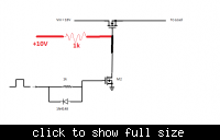
The control logic in fig1 generates a high(10v) or low(0v) signal to supply the gate of M2 to turn it off or on which will then turn M1 on or off. The mosfet M2 alone works fine with circuit shown in fig 2 but when I connect it with M1, M1 doesn’t turn on or off. What can be the problem? Do I need a driver circuit for M1?
 

Attachments

  • Fig 1.doc
    38.5 KB · Views: 169

Please post the complete circuit with the power supply and load.

The way you have it now there is no resistor connected to the drain of M2 so it can only ground the gate of M1 or leave it floating.
You need a resistor like fig2 that goes from drain to the positive supply but it will not work if you want to use M1 as a high side switch, the gate has to have a higher voltage compared to the source of the mosfet.

Alex
 
  • Like
Reactions: fshunj

    fshunj

    Points: 2
    Helpful Answer Positive Rating
If you try to use a Nmosfet as a high side switch and you drive the gate with the same voltage that you apply to the drain (or lower) then the mosfet will be in a half open state, depending on the gate threshold of the mosfet you will have an increased Vds voltage drop over the mosfet.
nmosfet_high_side.gif

To use it correctly you have to apply to the gate a voltage that is higher then the drain, this happens because when the mosfet turns on the source voltage will be almost equal to the drain (for example 10v), if you have applied that same 10v to the gate then you suddenly have no Vgs bias and this creates the problem.
See the correct circuit when a higher voltage (or a second isolated voltage) is used:
nmosfet_high_side_correct.gif

Notice the voltage drop on the first circuit which is wrong and the second which is correct.
The voltage drop depends on the gate threshold , it is lower for IRL2203 that has a gate threshold of 1v and higher for IRF640 which has a gate threshold of about 3-4v

The only other solution is to use a Pmosfet as a high side switch, then you don't need a higher voltage for the gate.

Alex
 
  • Like
Reactions: fshunj

    fshunj

    Points: 2
    Helpful Answer Positive Rating
yes,if you use a follower drive the load,and the gate voltage is lower then the drain ,the MOSFET is not completely on,than it will hot.So you also can ues a DC-DC source to drive the Gate.These problems are commonly seen in driving H-Bridge(if all are NMOS).

but if you put the load on the Drain,and the Source Grounding, it don't have this problem.

I sorry , my English is so poor:oops:.
 
I have attached the complete circuit. Load is a resistor of 5 ohms.
 

Attachments

  • Doc1.doc
    35 KB · Views: 170

If your transistor turns on by a voltage of 10V at the gate then I hope this circuit will do the trick.
 

I have attached the complete circuit. Load is a resistor of 5 ohms.

you need to use a resistor from the 10v to the gate of the output mosfet to be able to get some output but you will have the problem i have described above, high losses and voltage drop.
Unless you are able to drive the gate with a voltage at least 15v (5v above drain ) you can't use this circuit.
You either have to use a Pmosfet or you can use the output mosfet as a low side switch, providing gnd to a load that is connected to the positive power supply.

Alex
 

I have tried all these options of using two mosfets including pnos and low side nmos switch but none works. So now i'm trying to use a single high side nmos switch as shown. But still its not giving correct results. What can be the problem?
 

Attachments

  • Docc1.doc
    29.5 KB · Views: 151

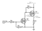
This is a circuit that works
Pmosfet_highside_switch.gif

but the point is for you to understand what you are doing in the circuit,
you have to use a resistor like R2 with provides positive supply to the gate when Q2 is of so that Q1 turns off too, if you don't use that resistor then the circuit can't work.
The mosfets were random models, you can use any models.
You can also use a NPN instead of mosfet Q2.
The voltages in the circuit show the on state when input is 5v,
I hope you are not switching in a fast rate because then you need higher current for the gate so that switching is fast.

Alex
 

I have tried all these options of using two mosfets including pnos and low side nmos switch but none works. So now i'm trying to use a single high side nmos switch as shown. But still its not giving correct results. What can be the problem?

I have already explained what is wrong with that in a previous post.
The Nmosfet turns on when you have a voltage applied to the gate that is higher than the source, you can't control your high side Nmosfet with 5v to the gate because as soon as it turn on you will have 10v in the source and then you have no bias so it turns off.

Alex
 

thanks alot alex for replying.
 

Status
Not open for further replies.

Similar threads

Part and Inventory Search

Welcome to EDABoard.com

Sponsor

Back
Top