lnm
Newbie level 4

- Joined
- Mar 17, 2011
- Messages
- 7
- Helped
- 1
- Reputation
- 2
- Reaction score
- 1
- Trophy points
- 1,283
- Location
- Madison, WI
- Activity points
- 1,372
I'm new to the forum, so I hope this post is in the right place.
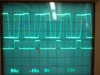
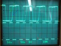
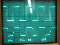
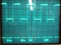
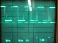
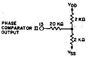
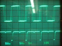
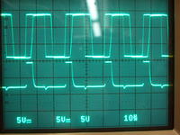
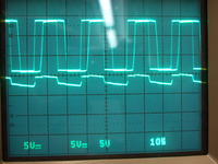
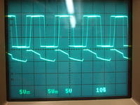
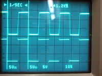
I'm trying to use the 4046's phase comparator 2, but the output isn't doing what I'd expect. Based on the **broken link removed**, I expect the output to be Vdd, Vss, or high impedance, but I'm only seeing very small output voltages even without any load attached to it (e.g. when it should be Vdd -- 15V in my circuit -- it's only a fraction of a volt). Everything else in the chip (VCO, phase comparator 1's output, etc.) seems to work fine, so I figured it was just a bad chip, but I just tried several different chips from two different manufactures and they all behave the same way.
Both of the input signals to the phase comparators are square waves that are something like 1.5V when low and 13.5V when high, so I don't think they'd be causing trouble (plus, phase comparator 1 doesn't have a problem with them). However, figure 3.4 on this German site seems to indicate I shouldn't have a rail to rail square wave input, although neither my German not google translate's English is good enough to tell me why (although it sounds like it's only an occasional problem).
Am I misinterpreting the datasheet? Is there some trick to making that output do its thing?
If there are no obvious tricks I should know, I can try capturing and sharing some oscilloscope traces to show what I'm talking about.

