bobsun
Full Member level 2

Hi All,
I would like to ask some questions on impedance.
If I am having 5mil wide track, how should I do to control its impedance to 50 Ohm?
Because when I am referencing a design, it found its Gerber files has specification that all signal lines needs to be impedance controlled to 50 Ohm, however I found in the PCB file that
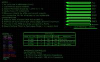
______________Material_______Thickness________Dielectric constant
Core__________FR-4__________12.6mil__________4.8
Prepreg_______ FR-4__________12.6mil__________4.8

Using a impedance calculation formula
Z0=(K / sqrt (Er+1.41)) * Ln (5.98*h/(0.8*w + t))
\[{Z}_{0}= \frac{k}{\sqrt{Er+1.41 }}\cdot \frac{5.98h}{0.8w + t } \]
I took K=79 because 5<w<15 (87 if 15<w<25), and
1. Er=4.8
2. h=12.6
3. w=5
4. t=1.4mil
Due to the table above, which resulted in 83.56 Ohm impedance as calculated by the formula, which is much larger than 50 Ohm.
There are several parameters in the formula and the one thing I am sure about is that 5mil width needs to be ensured, but how about other parameters? Do I have control over h, and is it the same as prepreg thickness?
I have another question over how “h” is defined. If the signal trace is adjacent to a internal power plane, is “h” the thickness of the prepreg or core layer between them? If the signal trace is not adjacent to any power plane, for example, signal layers on layer 3, 4 and 5, and a power plane on layer 6, then how should I define h for trace on layer 4, which are two signal layers separated between power plane 6?
And is GND plane also included in the definition?
Thanks,
Bob
I would like to ask some questions on impedance.
If I am having 5mil wide track, how should I do to control its impedance to 50 Ohm?
Because when I am referencing a design, it found its Gerber files has specification that all signal lines needs to be impedance controlled to 50 Ohm, however I found in the PCB file that
______________Material_______Thickness________Dielectric constant
Core__________FR-4__________12.6mil__________4.8
Prepreg_______ FR-4__________12.6mil__________4.8

Using a impedance calculation formula
Z0=(K / sqrt (Er+1.41)) * Ln (5.98*h/(0.8*w + t))
\[{Z}_{0}= \frac{k}{\sqrt{Er+1.41 }}\cdot \frac{5.98h}{0.8w + t } \]
I took K=79 because 5<w<15 (87 if 15<w<25), and
1. Er=4.8
2. h=12.6
3. w=5
4. t=1.4mil
Due to the table above, which resulted in 83.56 Ohm impedance as calculated by the formula, which is much larger than 50 Ohm.
There are several parameters in the formula and the one thing I am sure about is that 5mil width needs to be ensured, but how about other parameters? Do I have control over h, and is it the same as prepreg thickness?
I have another question over how “h” is defined. If the signal trace is adjacent to a internal power plane, is “h” the thickness of the prepreg or core layer between them? If the signal trace is not adjacent to any power plane, for example, signal layers on layer 3, 4 and 5, and a power plane on layer 6, then how should I define h for trace on layer 4, which are two signal layers separated between power plane 6?
And is GND plane also included in the definition?
Thanks,
Bob
Last edited:


