Continue to Site

Welcome to EDAboard.com

Welcome to our site! EDAboard.com is an international Electronics Discussion Forum focused on EDA software, circuits, schematics, books, theory, papers, asic, pld, 8051, DSP, Network, RF, Analog Design, PCB, Service Manuals... and a whole lot more! To participate you need to register. Registration is free. Click here to register now.

MAX7219 not quite man enough!

Status
Not open for further replies.

Damnthistinleg

Newbie level 3
Newbie level 3
Joined
Feb 24, 2011
Messages
4
Helped
0
Reputation
0
Reaction score
0
Trophy points
1,281
Activity points
1,357
Hello, this is my first post here so please go easy on me. Although I have a bit of knowledge, it's more space than mark - if you see what I mean!

Anyway, I'm working on a little project for which the MAX7219 is almost ideal. I need to drive 8 large seven segment displays but they require more power than is available directly from the 7219.

Although no datasheet is available for the displays, each segment appears to use four high-brightness LEDS in series with a 100 ohm current limiting resistor. I suspect from this that they are intended to be driven by 12 volts DC. I would like to take advantage of the PWM dimming facility on the MAX7219 so I need to do two things. Firstly, I reckon I'll need to drop the resistor value to around 27 ohms to increase the current through the LEDs, as they will now be pulsed. Secondly, I'll need to amplify the output from the 7219 in order to provide the appropriate voltage and current.

The problem is that I need to do this as efficiently as possible as I want to run everything from a 12 volt battery.

Many thanks in advance for any help!

Dave.
 

Thanks but the 7219 datasheet isn't a problem and I don't need one for the displays as I traced them out. I'm really looking to find the best way of driving them without using something inefficient like a Darlington array.

Dave.
 

The data sheet shows how to use the digit drive with external FETs when using large displays. If that still isn't enough, you can use transistor drive on the segment signals as well and still retain the PWM dimming control.

Brian.
 
Aah, I see. I missed that bit.

I've had a look at it but I don't think it's going to help in my case. The MAX7219 requires 5 volts and the digit requires 12 volts. The MAX394 doesn't appear to be able to handle the difference between supply voltage and switched voltage and in any case, the max current through the switch is 100mA.

I've now slept on it however and may have a simple answer. The problem is really the fact that the displays are common cathode. If they were common anode and I switched the 0 volt side, I should be able to use a simple NPN switch which could still take advantage of the PWM dimming on the MAX7219 with a minimum of components. It would also solve the problem of switching a higher voltage. With that in mind, it's probably easier to desolder the LEDs in the digit and turn them round.

Does this sound right?

Dave.
 

The polarity of the MAX7219 signals only allows use of common cathode displays, be careful if you just switch one side, particularly if you invert the signal or you will find all the digits except the one you want are displayed simultaneously!

I would be inclined to stay with the same digit drive circuitry (the ground side) but raise the anode side from 5V to 12V. The problem with this is it uses more components, you probably need two transistors, one driven by the anode (segment) drive and one 'hanging' from the 12V supply line. Each would invert the signal bringing it back to the correct polarity.

By coincidence, I have a design project underway which uses the MAX7219 to drive 64 individual LEDs and another project in the pipeline which uses 8 x seven segment LEDs but has to drive them at very high brightness so I may be facing a similar problem as you.

Brian.
 
You should consider using source drivers like UDN2981 or darlington arrays like ULN2803 for CA or CK type 7 segments.
 
Thanks Abidr,

The UDN2981 looks ideal for this application - assuming it can handle the current. At 12 volts, I'm looking at an individual segment current of 100mA but this is at a duty cycle of about 10%. I notice that the recommended maximum output rating of this chip is 350mA but there will be occassions where all seven segments and the decimal point are in use; thereby coming to 800mA. I'll just have to get hold of a few and try them out!

I've used ULN2803s in the past and know that you can 'pair up' inputs to increase current handling. I suspect the same is true for the ULN2981 so that is a possibility.

If the current handling or the component count remains an issue, I suppose I could always rewire the digit to run with 8 LEDs in series. I'd need to be supplying/switching 24 volts but at least the current would be halved. It's quite easy to get hold of large 24 volt batteries too. Just a thought!

I'll dig out the veroboard and get back to you all. Thanks for the advice so far!

Cheers,
Dave.
 

Yes UDN too can be paired like ULN2803.
I did paired three of them together and it worked flawlessly, only catch is UDN is 4 times more expensive than ULN2803 in my country.
No regrets though, its convenient to solder a DIP 16/18 than 8 transistors or FETS
 
Hi.

I'm looking for a solution to almost exactly the same problem. I need to drive common cathode 3 inch 7 segment displays with a MAX7219. Each segment requires 9V 20mA. So, as opposed to the original poster, I'm still well within the max 40mA per segment that the MAX supports. I only need higher voltage.

So I guess I can just use the MAX digit sink side but need to add components to the segment source sides.

I read the suggestions on this thread but can't quite picture in my head how to do this. Does anyone have a diagram of the solution, please?
 

To sink you could use ULN2x03
and for source you could use UDN2981.
 
  • Like
Reactions: yesyes

    yesyes

    Points: 2
    Helpful Answer Positive Rating
Thanks for that.
Since I'm within 40mA I assume the sink side (digit drivers) can be used directly, is that correct?
So I only need to put one UDN2981 into the segment lines and put 9V and ground onto the UDN2981?
 

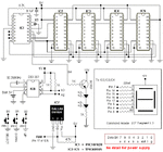
If you could get TPIC6B595 then attached circuit is very good. Its an RTC clock.
Its a common anode based RTC.
Since I have not been able to find common cathode 7 segments in my country, therefore, I have always made circuits based on C.A.

BTW: This is not my project, found it on the net, about a year ago, I made it for 2.3 inch 7 segments and it has been working flawlessly eversince.
 

Attachments

  • clock.gif
    clock.gif
    20.8 KB · Views: 365

To sink you could use ULN2x03
and for source you could use UDN2981.

I made a schematic adding the UDN2981 to the segment drivers. Could you please have a look at the attached schematic and see if I understood this correctly?

Is it OK to sink the LED current through the digit drivers of the MAX or would it be absolutely necessary to add another external driver there?

Thanks!
Chris
 

Attachments

  • MAX7219 high voltage LEDs (Schematic).pdf
    29.3 KB · Views: 199

Technically at a glance, the schematic is alright.
But honestly I have never tried it, so I can say for sure it will work.
Just to be on the safe side I "personally" would prefer using a sink driver like 2803 as well, since you are using a 12 volt supply, so I would assume the 7 segments are in excess of 2.3 inch size.
 

yes, they are 3 inch displays. 6 LEDs in series for each segment (2 for the decimal point).

So I would add a ULN2803 into the digit lines just like the UDN2981 but connect pin 9 to ground and pin 10 to the same 12V supply as the UDN2981?
The 12V voltage should have dropped to zero at this point through the limiting resistors and the LEDs. So this driver would only be required to sink more current than the MAX can handle, right? The MAX7219 datasheet says that the digit drivers can sink 320mA. With 8 segments at 20mA each it would run at 160mA if all segments are on. This should be well within the specs. Would you add the 2803 just as a precaution or is there another reason I can't see at the moment? ;-)

I think my initial problem in my thinking was that I thought the segment current needs to flow from the segment drivers through the LEDs *back* to the MAX digit drivers. But it seems they are just logic levels after all but with constant current sources in the segment drivers.

Regarding the constant current sources in the segment drivers, does this need special attention, like resistors between the MAX7219 and the UDN2981? Or can I just treat then as normal logic level outputs anyway?
 
OK, I changed the schematic to include the ULN2803. Actually 2 of them. Since the ULN2803 is inverting I had to invert the inputs again. I prefer to use another ULN2803, mostly because I prefer its pin-out to, say, a couple of 7404s.

Do you think this will work this way?

I ordered a few ULN2803 and UDN2981 from China (a lot cheaper!) but will have to wait a month or so for them to arrive before I can test this out.
 

Attachments

  • MAX7219 high voltage LEDs (Schematic).pdf
    41.5 KB · Views: 181

Nicely drawn!

Only two comments:

You may not get enough drive current into the second 2803 unless you drop the 4K7 resistors down to 2K2 or less, a better solution would be to use a TTL or CMOS inverter instead of the first 2803. Remember these devices can only sink current, they can't source it so you are relying on the 4K7 to provide all the bias to the second 2803.

Be careful with the decimal point signal, it probably needs a value higher than 150R to limit the current as there will be fewer LEDs inside the display module.

Incidentally, you don't need to connect the VCC pin on the second 2803, the device does not draw current so it needs no supply! You could connect the pin through a switch to ground, when closed it will turn all the digits on at the same time for testing purposes.

Brian.
 
  • Like
Reactions: yesyes

    yesyes

    Points: 2
    Helpful Answer Positive Rating
Thanks for that. I'm using DesignSpark for my schematics now. It's free and a lot more fun than, say, MS Paint. :D

I thought I had calculated the 4k7 pull-ups for the 2nd 2803 from the datasheet. Vin 3.85V / Iin 1mA = 3.85kOhm. But I have probably not fully understood that datasheet for the 2803. Once they arrive I'll test this on a breadboard with different values.

I had chosen another 2803 as inverter because of its far more convenient pin-out where in and out are opposite each other. This circuit will in the end be done on Vero style strip board and the 2803 pin-out would make that so much easier compared to a 7404 for example.

You're right about the decimal point. It's only 2 LEDs and runs at 4V 20mA. I changed that one resistor.


I had another thought last night. Since the segment drivers of the MAX7219 are constant current sources, wouldn't I need to put a resistor from each line to ground so as to allow that current to flow? I doubt that the 2981 would sink that current. If I set the MAX to source 3.5V 10mA, the resistors would have a value of 350R.

I changed the schematic accordingly and attached it.
 

Attachments

  • MAX7219 high voltage LEDs (Schematic).pdf
    45.4 KB · Views: 1,547

Your calculation is upside down! If Vin is 3.85V and the supply is 5V, the resistor has to drop (5 - 3.85) = 1.15V at 1mA which makes it 1.15K.

I would be inclined to try it without extra load resistors and add them if needed, Maxim don't show the output driver schematic so it's difficult to tell what might happen.

Brian.
 
  • Like
Reactions: yesyes

    yesyes

    Points: 2
    Helpful Answer Positive Rating
Status
Not open for further replies.

Part and Inventory Search

Welcome to EDABoard.com

Sponsor

Back
Top