Continue to Site

Welcome to EDAboard.com

Welcome to our site! EDAboard.com is an international Electronics Discussion Forum focused on EDA software, circuits, schematics, books, theory, papers, asic, pld, 8051, DSP, Network, RF, Analog Design, PCB, Service Manuals... and a whole lot more! To participate you need to register. Registration is free. Click here to register now.

[SOLVED] AM superhetrodyne reciever

Status
Not open for further replies.

sadatwins

Junior Member level 2
Joined
Apr 24, 2010
Messages
20
Helped
1
Reputation
2
Reaction score
1
Trophy points
1,283
Location
jordan
Activity points
1,414
can i make AM radio with 1.5 volts without using an IC or i can replace it in design by its components???
 

you can make simple AM radio just by using the few components. MW antenna coil with a detector diode and one or two transistors....But it will not be a superhetrodyne receiver... It could pickup only nearby stations only and the SNR will be low...And if you try to increase the gain then distortion also increases...Just try to amplify the selected RF signal(connect variable capacitor with mw coil and tune it to required frequency to select the channel) using a single stage transistor amplifier. Dont use any capacitor in between EB and EC of the transistor since because the high frequency RF signal will be bypassed through the capacitor... Use a very low capacitance (say 10pf) to couple the RF signal picked by the MW coil to the base of the transistor.
Then just connect a detector diode at the output of the amplified RF output at the collector of first transistor. Then amplify the audio signal using another transistor...I just done this and i got some radio stations very clearly....(am not comparing it with superhetrodyene)

---------- Post added at 19:04 ---------- Previous post was at 18:55 ----------

tomorrow i will draw and upload the circuit diagram...
 
Last edited:
Did you mean Super regenerative receiver? This is a simple circuit, which is like a RF amplifier with a small amount of POSITIVE feedback applied to it. This has the effect of increasing the gain of the stage and increases its selectivity. The downside is it is difficult to make it stable and for maximum gain you need to twiddle the tuning capacitor and adjust another control called "reaction"
Frank
i meant superhetrodyne
 

If you do mean a hetrodyne (ie beat with an oscillator) then there are two basic types.

The first is the on frequency oscillator used in a direct Conversion (DC) reciever. These receivers although simple have a number of problems the first and formost being the stability of the oscilator with respect to the AM signal that produces an overriding beat note which swamps the signal from the AM side bands. Thus for simple systems a DC system is not recomended even though it can be implemented with a single dual gate fet.

The second type of hetrodyne reciever uses an off frequency local oscillator (LO) with an intermediary frequency (IF) that is fixed which can consiquentlyy use very narowband filters to remove other interfering signals and thus have very high gain stages. The output of the IF strip is then put into a detector circuit of some kind.

For most AM receivers the detector used is an envelope detector although in complex systems synchronus circuits can be used to create the equivalent of a phase controled DC receiver.

The IF frequency can be either above or below the signal frequency and or local oscilator, often it depends on the receivers input coverage as to which is benificial.

Because it is easier to design very narow band circuits at low frequency sometimes a hetrodyne reciever actually has two IF's the first being high frequency and of a broad bandwidth (ie 100MHz@1MHzBW) which then gets mixed with the second local oscilator down to 10.7MHz or even 455KHz which in the case of some communications receivers could have a bandwidth of 100-300Hz for morse or other slow data rate signals.

The simplest hetrodyne receiver for Broadcast AM (0.5-1.6MHz) is one using a 455KHz IF frequency and a high side oscillator (1Mhz-2MHz) however this has a real problem in that when the LO is at 1MHz the receiver will pick up both a 0.545MHz signal and a 1.455MHz signal at the same time. The solution that you see in nearly all simple Broadcast AM receivers is to make the front end tuned as well as the oscilator. However the tuned front end and local oscilator need to track each other which means using a "dual gang" variable capacitor however the change in cap value is not a linear one.

Before going into any more depth I think you should let us know the frequencies you wish to use the bandwidth of the signals the channel spacing and if you need to use a preselector front end or not.
 
...and what chuckey describes is a "regenerative" receiver, not a "super regerative" one which works quite differently.

There are IC radios that work on 1.5V, for example the ZN416 and MK484 which are TRF types but can directly drive headphones or a small loudspeaker.

Brian.
 
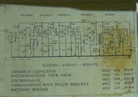
thats the circuit i'm working on
i'm trying to figure out why do we use each stages, i found similar schematic but with 2 IF amplifying stage(instead of 3 amplifying) stages as result the one with less IFT needs more voltage
so i was wondering if i add an extra stage will i be able to use 1.5 instead of 3 volts??check pictures below
 

No, I think so, that it's not needed a third IF amp. stage, your first circuit should be work with 1.5 v.
Set the transistor currents as in picture (with the basic resistors).
Use Ge NPN transistors in the push-pull end-amplifier if needed due to the low voltage.

The other circuit is interesting (mixing NPN and PNP) but not really suitable for low voltage operation.
 
i'm wondering if i want to find values for capacitors connected to IFT should i use nominal inductance value & substitute it in (1/2Pi*(LC)^.5)
 

Sadatwins,

The main issue you have initialy is adjusting the bias points in the circuit. This may be a significant issue in most of the stages as they are "self" or "current" biased thus the resistors from the supply rails to the device bases will almost certainly need to be adjusted.

The first thing you have to remember is that Vbe of silicon transistors is ~0.7V at room temprature which is half your supply voltage which is going to cause you a voltage overhead issue and the circuit shows the bias points as being outside this voltage range. Which as germanium devices are now quite rare why many very low voltage circuits are FET based.

The circuits you show have four basic sections.

1, Self Oscillating mixer.
2, Multi stage IF strip with AGC
3, Combined audio detector and AGU control generator
4, Audio amplifier.

Once the bias points have been fixed the next issue is where if anywhere is any extra gain needed?

The first stage consists of a self oscilating mixer with the antenna being an "on frequency" tuned stage with the ferite rod core being the method the RF field is coupled into the receiver. Thus the gain can simply be improved by increasing the size of the feritte rod or finding some way of increasing the field it couples into. You could simply add an idler turn around the rod that is connected to a long wire antenna or other kind of RF amplifier and antenna.

You could also improve the gain by playing with the tap point of the transistor on the collector tuned circuit which is tuned to the IF frequency. You will probably need to adjust the number of turns on this inductor anyway due to the 50% reduction in supply voltage to ensure you get the device to socilate at the emmiter tank frequency reliably.

The way to get this stage reliable is to first disconnect the input tuned circuit by connecting the base directly to the bias resistor, then replace the IF tank circuit with an appropriate load resistance that supplies the same current into the collector LO feed back coil to the emmiter LO tank.

You then replace the load with the IF tank circuit. You can increase the gain of this IF tank circuit by changing the tap point on the IF tank circuit coil or by changing the ratio of the turns from the IF tank to the coupling loop to the next stage.

I would, as the IF strip has an AGC loop from the detector not look to change this circuit unless you have to. The reason for this is the diode detector and lowpass filter used to recover the audio also supply the AGC DC feedback voltage that changes the bias point thus gain of the first device in the IF strip.

The AGC voltage is subtractive that is the detector diode produces a negative voltage that is used to supply voltage bias to the first IF transistor. As the signal level increases an increasingly negative voltage takes the bias voltage of the first IF transistor down effectivly turning it off via the lowpass filter formed by the 2k2 resistor and electrolytic cap down to ground.

The simplest way to add gain is to either change the turns ratio on the audio output transformer, and/or to change how the audio transformer primary is driven. If you change this to a bridge driver then you will get double the voltage swing and for times the power into the primary turn.
 
Status
Not open for further replies.

Similar threads

Part and Inventory Search

Welcome to EDABoard.com

Sponsor

Back
Top