sirod_123
Junior Member level 1

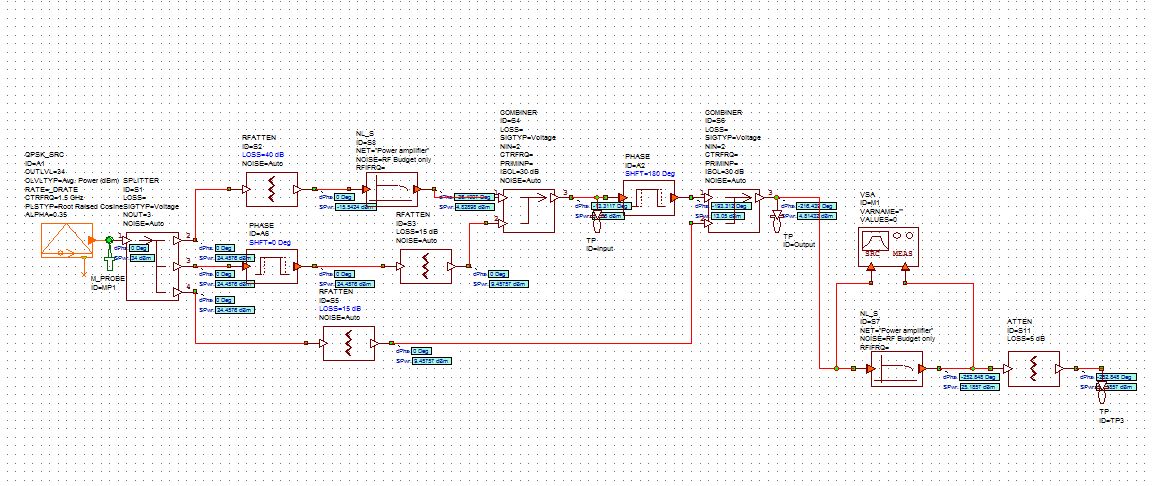
I'm trying to design a predistorter for Class AB amplifier and I found an example from MWO predistorter example. I tried to apply the simple structure to my class AB amplifier but the result is quite wired.
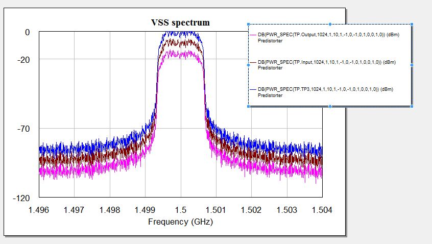
As can be seen from the pictures attached, the blue line is the output from the the last attenuator, the brown line is the output from the first combiner (starting from left), the pink is the output from the second combiner.
I have a couple of questions:
1) The three ACPR remain exactly the same shape with different power with out any IMD band. Could anyone help?
2) In addition, wondering if it's possible to do two-tone test in system schematics? and how? cause I think ACPR is a bit complex to analyze the IMD effect.
3)Is it possible to do a characteristic plotting for the predistorter in the system schematics? I was thinking about comparing the inverse characteristic of the amplifier.
4) How do I relate the phase change at each node to the AM/PM improvement?

Thanks a lot
As can be seen from the pictures attached, the blue line is the output from the the last attenuator, the brown line is the output from the first combiner (starting from left), the pink is the output from the second combiner.
I have a couple of questions:
1) The three ACPR remain exactly the same shape with different power with out any IMD band. Could anyone help?
2) In addition, wondering if it's possible to do two-tone test in system schematics? and how? cause I think ACPR is a bit complex to analyze the IMD effect.
3)Is it possible to do a characteristic plotting for the predistorter in the system schematics? I was thinking about comparing the inverse characteristic of the amplifier.
4) How do I relate the phase change at each node to the AM/PM improvement?
Thanks a lot
