steadymind
Full Member level 4

500MSPS is high sample rate and you probably can use time interleaved DAC architecture to give ur charge redistribution dac more time to settle. what specs are u targeting for ?
Follow along with the video below to see how to install our site as a web app on your home screen.
Note: This feature may not be available in some browsers.


Because the glitch amplitude depends on the C-ratio. The C values don't change by changing the slew rate.... if I increase rise time (also fall time) of control signal by two times why doesn't amplitude of glitch reduce by 2 times?

Bottom plate sampling only forces all (or at least the majority) of charge injection towards the same node of the switch, which can be later cancelled off via differential circuits. It does not reduce any "glitches". Furthermore, it does not handle the other non-idealities.@checkmate:Even with bottom plate sampling I'm getting signal dependent glitch!!how to over come this issue.
And even size of dummy transistor is effecting amount of glitch by few tens of volts.Should the size of the dummy transistor be always half the size of main switch always?
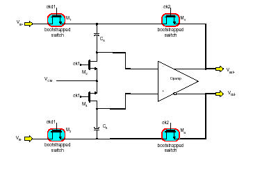
The maximum sampling rate is largely determined by the settling time of the opamp.In the circuit shown below will the GBW of opamp determines the maximum sampling rate DAC?
so any transient coupling will be less obvious when slew rates are reduced.
Lastly, if you are still using 5fF caps, your only option is to either reduce parasitics, or increase your cap
- your switch isnt designed properly...I've changed my capacitance to 20fF but bootstrap switch isn't tracking input signal
Then have you considered that you are targeting a sampling rate that is so high that it is not achievable by your process?I've changed my capacitance to 20fF but bootstrap switch isn't tracking input signal.And if size of bootstrapped transistor is increased so as to drive the capacitor it is resulting in larger glitches at capacitor top plate.
Switch I've used has been attached earlier,If you have any experience with circuit can you please explain how to improve that circuit,because for 5fF capacitance it is working quite wellyour switch isnt designed properly...

I've changed my capacitance to 20fF but bootstrap switch isn't tracking input signal.And if size of bootstrapped transistor is increased so as to drive the capacitor it is resulting in larger glitches at capacitor top plate.
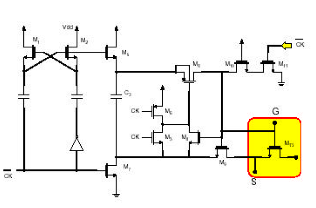
But dummy transistor should be fed with inverted control signal,then how can I generate inverted signal as the bootstrap switch is controlled by some complex circuitary....Adding dummy transistor helps to reduce charge injection and clock feed-thru. As the result, the glitch will be suppressed.
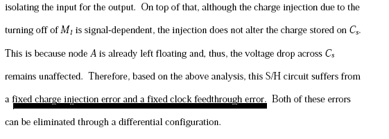
@checkmate:In document you have suggested it is said that we will have only fixed charge injection and fixed feed thru,but I'm getting signal dependent charge injection.Bottom plate sampling only forces all (or at least the majority) of charge injection towards the same node of the switch, which can be later cancelled off via differential circuits. It does not reduce any "glitches". Furthermore, it does not handle the other non-idealities.
Does interleaved architecture mean using two parallel ADCs?You should really try to evaluate alternate architectures, or try some sort of interleaved architecture to lower your sampling rate.