Continue to Site

Welcome to EDAboard.com

Welcome to our site! EDAboard.com is an international Electronics Discussion Forum focused on EDA software, circuits, schematics, books, theory, papers, asic, pld, 8051, DSP, Network, RF, Analog Design, PCB, Service Manuals... and a whole lot more! To participate you need to register. Registration is free. Click here to register now.

[SOLVED] Clean-up Pulse for RB0 interrupt.

Status
Not open for further replies.

biboymusic

Junior Member level 1
Joined
Jan 7, 2011
Messages
16
Helped
0
Reputation
0
Reaction score
0
Trophy points
1,281
Activity points
1,430
Hi,

I need help on cleaning up pulses from my hall effect sensor. The project is a wheel speed sensor.

4 magnets on the wheel hub, 1 hall effect sensor on the front fork. That means, 4 pulses/wheel rotation. However, using a simple program on the PIC to count each pulse gives me unpredictable results. As each magnet passes, I get like 100+ counts, very random numbers. Doing manual interrupts on RB0 perfectly counts pulses, using the hall effect sensor gives me random numbers.

Using a Multimeter on the hall effect output, I get +5v and 0v on each magnet pass. So I think I need to clean up the pulses to perfectly give me 1 count on each pass on the magnet.

Any ideas? OpAmp maybe?
 

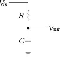
Most commonly Low pass filter is sufficient.I solved this problem in my application with LPF.Place an LPF with suitable RC combination.
 
Im not really good with analog circuits. Can you give me a sample schematic for LPF? I presume its a circuit I can put in between the output of the hall effect sensor and RB0 port. Thank you.
 

it is a very simple circuit the RC values may differ for with application(time constant ,cutoff frequency ).


One simple electrical circuit that will serve as a low-pass filter consists of a resistor in series with a load, and a capacitor in parallel with the load. The capacitor exhibits reactance, and blocks low-frequency signals, causing them to go through the load instead. At higher frequencies the reactance drops, and the capacitor effectively functions as a short circuit. The combination of resistance and capacitance gives you the time constant of the filter τ = RC The break frequency, also called the turnover frequency or cutoff frequency (in hertz), is determined by the time constant:

Cutoff frequency (Fc) = 1/(2 pi RC)
39_1297165822.jpg
 
I actually did that. I've searched google and found out about it. With this filter, would I miss some pulse? I did a 1.5k ohms R and 2.2uF C. I should be able to capture pulses upto 200 pulses/sec. Tested the speed, and at 64 km/hr I am already moving very fast like 100+ km/hr.

Thank you.
 

Better to give the Sensor speed in RPM & CPT(counts per turn).instead of km/hr.
i used 1.5K & 100nF combination.It might be suitable for your application.But not sure.
i given my circuit RC values
 

My C value is so large that I actually miss some pulse on high speed. Reduced to nF values gave me better results. It is working perfectly now. Thank you so much for your help.
 

Status
Not open for further replies.

Similar threads

Part and Inventory Search

Welcome to EDABoard.com

Sponsor

Back
Top