eem2am
Banned

Hi,
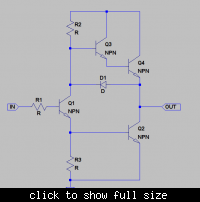
I have come up with two cheap FET gate driver circuits for driving the gate of a power mosfet in a switch mode solenoid driver.
The PWM signal is provided by the output pin of a microcontroller.
The solenoid current is 200mA.
The FET Vgs(th) should be between 0.8V and 3.5V
****************
Complimentary pair gate driver schematic:-
https://i56.tinypic.com/2zh136o.jpg
...the above "Complimentary pair gate driver schematic" gives a slow turn off of the FET since there is a lingering Vce(sat) voltage of the PNP BJT.
...here is the FET gate voltage showing the slowly declining FET gate voltage at turn off..........................
FET gate voltage with complimentary pair drive:-
https://i52.tinypic.com/xn5h8z.jpg
.....in order to make the FET turn off quicker, the following adjustments were made.................
*******************
Adjusted Complimentary pair gate driver:-
https://i55.tinypic.com/v7t5sj.jpg
having the diode D2 in the Adjusted Complimentary pair gate driver gives a faster turn off of the FET.
..................the diode D2 in the "Adjusted Complimentary pair gate driver" also ensures that there is no shoot-through current by 'slamming' off the PNP BJT when the NPN conducts.
I assume that since the driver devices are BJT's, they will offer more resilience to transients coupled through the Drain-Gate capacitance than circuits which directly drive the FET from the microcontroller port.?
(its my belief that its FET gates that are the most susceptible thing to damage by transients and ESD....BJT's are more robust?)
Does any reader know of a technique of adjusting the above schematics so as to make the FET gate voltage go to zero quicker when turn-off occurs?


