AleXYZ
Junior Member level 3

I am trying to create a portable EL-wire driver that can handle a wide range of wire lengths, up to 100 feet if possible. EL-wire takes roughly 50mW per foot to glow brightly. I've been designing buck converters successfully for about 2 years now, so I thought this would be easy. But....
I am having a problem boosting 7.4 volts to the needed 75 volts. When I do get 75 volts, my bench experiments yield virtually no usable current.
Here are the details:
* Unit will be battery powered, from 2 LiIon cells for a working voltage range of 6-8.4v.
* I am using a dual H-Bridge (already prototyped and tested) to convert +75v to 120 VAC at 400-1500 Hz.
* Unit must be pretty small, in other words I'd like to avoid big heavy transformers if at all possible
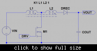
* +75v rail must be actively regulated (see circuit)
* Max. output from inverter needed is 75v @ 0.1A which should be enough to power about 100 ft of El-wire
* Want to make the inverter from SCRATCH, not buy an off-the-shelf unit
* I will probably use a newer model PIC microcontroller to handle any PWM timing requirements (the H-Bridge needs it anyway)
Here are the three topologies I've considered:
* Switched-capacitor. Problem is, I haven't found any devices that can go above 30v. Also, their output wattage is somewhat low.
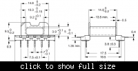
* Flyback transformer. May be my best bet, but haven't found a transformer small enough for the job.
* Boost converter. This is the route I'd prefer to take. BUT. In my bench experiments I have not been successful (see below) and although I can achieve 75v, I cannot get more than a milliamp or two.
My Boost Converter Experiments:
For the math and circuits, I used these two websites to calculate the inductor and frequency:
Make a simple boost converter
Coilcraft - RF chip inductor, power inductor, power magnetics, and other inductors
Since I have a lot of 100uH inductors left over from my buck converter projects, I decided to experiment with those. I chose a frequency of around 15 kHz which yielded a duty cycle around 90%. So far so good. The attached circuit is sitting on my desk right now. I am using an Agilent U8002A power supply instead of batteries. I have a frequency generator set at about a 85% duty cycle and a full range of frequencies to play with.
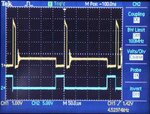
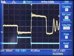
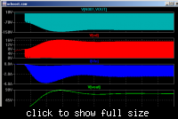
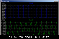
The circuit as shown gives me only about +30-35 volts, and I have to tune the frequency to find it. The best output occurs at around 4 kHz. This morning, I replaced the Darlington transistor arrangement with a power MOSFET and got better results. It kicks up to +60 volts when I tune it to 2.5 kHz, but still no usable current. As soon as I load it with the H-Bridges, the voltage collapses to about 12 volts... and that's with only 1 foot of El-wire attached!
By pushing the limits on the U8002A to 7.25v and 0.4A, the output will hit about +50 volts and the El-wire just barely begins to glow. But that means I'm pushing almost 3 watts of current into the boost converter and getting less than 50 milliwatts out. The components are all rated at 100v or greater. The MOSFET gets a little warm, though not much. The inductor and diode stay cold. Where is all that energy going?
What To Do?
I am not committed to using a boost topology for this project. If anyone has a suggestion how to get the needed voltage with decent current, I'm all ears. Or if you have an idea how to fix my buck design to get higher current yield, I'd really like to know.
75 volts at 100 milliamps? Anyone?


