gilbertomaldito
Full Member level 3

Hi
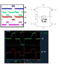
Attchde in this file is an image showing an H-bridge circuit with a brushless DC motor load. It can be see nthat the Hbridge is driven by a non-overlapping control signals. Shown on the lower part pf the circuit is the waveforms for the current and the motor drive voltage (O1-O2) I just want to ask why there is a huge overshoot in O1-O2 signal right after all the NMOS's and PMOS's closed?
I also want to ask how can I possibly verify the actual EMF of the motor load?
Thank you
andrew


