Continue to Site

Welcome to EDAboard.com

Welcome to our site! EDAboard.com is an international Electronics Discussion Forum focused on EDA software, circuits, schematics, books, theory, papers, asic, pld, 8051, DSP, Network, RF, Analog Design, PCB, Service Manuals... and a whole lot more! To participate you need to register. Registration is free. Click here to register now.

negative feedback becomes positive feedback?

Status
Not open for further replies.

sapphire

Member level 3
Member level 3
Joined
Nov 13, 2004
Messages
66
Helped
2
Reputation
4
Reaction score
1
Trophy points
1,288
Activity points
440
Hi,

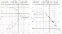
I am simulating the AC response of a unity-gain feedback amplifier using Spectre stb analysis. It works fine for most corners. But for some corners such as slow-fast(t=-40,125; vdda=2.05), the loop phase suddenly change to 0 degree at DC (it's supposed to be 180 degree). That means positive feedback! It's so werid. Is it a problem of spectre or a problem of the circuit? The simulation includes post-layout extraction.

Thanks
Sapphire
 

i think you may need to know the poles you have in your system and the system performance
in certain situations where the circuit is frequency dependent

A(feedback gain)=A(open loop gain)/(1+AB)

B factor depend on frequency
and it's phase can change as frequency
 

I am referring to open loop gain in my post. I put an "iprobe" instance in parallel with a 1GHz resistor in the feedback loop. Both are ideal devices only for simulation purpose. But I don't know what cause the sudden change of phase response. Magnitude response looks fine, only gradual variation.


i think you may need to know the poles you have in your system and the system performance
in certain situations where the circuit is frequency dependent

A(feedback gain)=A(open loop gain)/(1+AB)

B factor depend on frequency
and it's phase can change as frequency
 

I've seen this happen when the amplifier is not working right,
like the output can't drive the load and the front end has
swung outside the linear region trying to cover it. Small
signal analysis wants none of that.

Set yourself up an equivalent schematic minus the iprobe
and look at your input offset voltage, and current balance
in differential legs / gain mirror stages for starters.
 

I understand AC response as small signal analysis. In so far no overload and other non-linear effects would take place. Initial bias point may be a problem, aber also won't explain "sudden" changes. Can you please show a graphic example of "suddenly change". As far as I'm aware of, there can't be sudden phase changes without high Q complex poles.
 

The DC voltage at the positive terminal of the regulator is changed from 0.8 volt to 0.83 volt with 10 steps

 
Last edited:

Are you simply driving the regulator so far into dropout
that the loop can't close, or that it requires so much
gate overdrive that there's no small signal difference
between "buried" and "just about as buried"?
 

what do you mean by "the loop can't close"? Could you exlain a bit more? I don't quite understand what you means.

Are you simply driving the regulator so far into dropout
that the loop can't close, or that it requires so much
gate overdrive that there's no small signal difference
between "buried" and "just about as buried"?
 

I had the same problem last year see below

https://www.edaboard.com/threads/166558/

It has something to do with the mismatch and not solving a new DC operating point within the Monte Carlo analysis is my understanding. Also If you just simulate process only it is gone. It only happens with Middlebrook and cadence STB method (tian method). I truly believe it is a bug in cadence AC simulations, but I have not gotten a better answer to this....
I taped out my chip and it works 100% even thou I had the same problem you have.

Do your transient response in how your amplifier will be used over monte carlo and it should be fine, unless you have another problem..
The transisient response is the true indicator of stability! You would never use your amplifier open loop AC :p

hope this helps
Jgk
 

Without knowing the circuit and it's operation point details, I won't say it's a bug. It may be normal operation by design of the circuit.

I previously misunderstood suddenly as a sudden change over frequency. But the frequency characteristic of each parametric plot is pretty plausible. The only question is, why the transfer characteristic changes "suddenly" over operation point. If you imagine a transistor switch in the circuit, it's quite reasonable. So you have to analyze the signal path to see, where the sudden change happens. Besides a stage "switching" on and off it can be also a case of signal superimposition from parallel pathes, that cancel out.

Monte Carlo analysis requires calculating a new operation point for each iteration in my opinion, and the tools I'm working with are doing it. But depending on the circuit, the different operation point may be just the problem.
 

I would think that if a stage is "switching" on and off or transistors going into triode you would see your open loop gain drop by alot. From the above plots I would say you are open loop gain is around 80ish and yeah some monte carlo runs will give you 100dB like you have... but I don't think thats a stage "switching off/on".....I really think this is a bug because when running the same amplifier as a buffer or whatever you are using it for and you put a step response in there and monte carlo 1000 runs not a single one will oscillate which would be that phase starting at 0 going up 90, then meeting with the other plots...I agree it is funny and thus some kind of bug, but its only with middlebrook and STB(tian method) If you do the old school close loop with low pass filter, large cap on Vinm and 100Gohm resistor in feedback, then AC open loop test your amp, you don't see these funny phase jumps... well atleast not with the amplifiers I tested this with... That is why I think its a bug....
Jgk
 

Thanks all for the replying! I don't have switching stages in my circuit. From the transient response, it looks fine. So it's most likely due to some weird software problem. In my simulation log, it shows "Finding DC approximate solution failed". But without a DC op, how can the simulator proceed with stb simulation (like AC)?


For your information, I also got a similar answer from designers-guide forum. It's very interesting to see his simulation plots from a simple concept circuit, almost the same as mine.

The Designer's Guide Community Forum - negative feedback becomes positive feedback?
 
Last edited:
  • Like
Reactions: jgk2004

    jgk2004

    Points: 2
    Helpful Answer Positive Rating
Thanks for the link! I am happy to read it does not mean an unstable circuit but just an issue do to not having the Iprobe in the correct spot which results in not all the feedback loops being broken! I will definitely look into finding the correct place to break my loops so I don't have to look at this plots issue again! Once again thou, the Transient shows the true response so always do that with your AC simulations!
Thanks again for that link!
Jgk
 

Status
Not open for further replies.

Part and Inventory Search

Welcome to EDABoard.com

Sponsor

Back
Top