Continue to Site

Welcome to EDAboard.com

Welcome to our site! EDAboard.com is an international Electronics Discussion Forum focused on EDA software, circuits, schematics, books, theory, papers, asic, pld, 8051, DSP, Network, RF, Analog Design, PCB, Service Manuals... and a whole lot more! To participate you need to register. Registration is free. Click here to register now.

1500W Inverter Full Schematics And Pcb

Status
Not open for further replies.


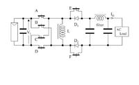
I propose the new type transformer less inverter whose basic topology should be
buck boost converter. The greatest characteristic of this inverter would be that it will has only one stage to generate
AC power. It means that simple circuitry can be realized. The control method for the proposed inverter
using the particular characteristic of buck boost converter. To control duty ratio of the
main switches, the wide range voltage matching is feasible.

looking for comments and citation.:razz:
 
  • Like
Reactions: dielli

    dielli

    Points: 2
    Helpful Answer Positive Rating
what are input and out put volts.
 
pnjbtr i will post complete proj in a day r 2 .
 

pnjbr how about to use this on for osi (experimental Pure Sine Wave 50Hz)
 
pnjbr how about to use this on for osi (experimental Pure Sine Wave 50Hz)
I think we can not gain optimal power from IRF250 with Dc 12v.Because its RDS is 85mil ohm,operating volt 200,difficult to saturate.with 12v dc.
IRFP150 is better instead of 250.
Bd140(pnp),needs postive volt at Emmiter.
12+12/230 does not suits for 12v battery.
i think max 10.5+10.5/240 volt transformer is better.
 
i think max 10.5+10.5/240 volt transformer is better.
Not good enough. The peak voltage of a sine-wave is 1.414 times its RMS voltage. So a 230V transformer needs the low voltage winding to be less than 12V/1.414= 8.5V. Maybe use a 8V-0-8V transformer.
 
  • Like
Reactions: simeo

    simeo

    Points: 2
    Helpful Answer Positive Rating
And the mosfets will switch off rather slow.
 

Look at the two 6A diodes that short-circuit the transformer. When one side is driven to ground by the Mosfets on its side then the other side of the center-tapped transformer winding must swing up to +24V but the diodes prevent it.
 

Hi Audioguru without those diodes your mosfets will be destroyed within the first cycle, in any case you all beat around the bush, you can't change the frequency of a signal after it is generated. The only way to change the signal from the high frequency of your first stages, is to rectify and smooth your signal and then convert your DC back to 50Hz AC.
That is the same reason why a FM transmitter is modulated right at the first stage where the RF signal is generated, not like an AM transmitter, that is modulated at the final stage where there is no frequency modulation taking place, only the amplitude.
 
Last edited:

A Mosfet has a very high power zener diode as part of its structure so a little flyback spike when there is no load won't bother it.

The diodes across the center-tapped winding are a dead short to the output of the inverter because the center-tapped winding must act as a teeter-totter. When one side goes to ground then the other side must go to twice the supply voltage due to transformer action. The center-tap is the hinge at +12V.
 
  • Like
Reactions: JanIan

    JanIan

    Points: 2
    Helpful Answer Positive Rating
I don't think it is a little flyback spike, it can run very high so high that even the zener can be destroyed but I still cant see how you can get a pure sine wave from that diagram, it is a lost course.
 

We don't know the programming but maybe the Mosfets are fed a high frequency PWM signal that is modulated by a low frequency sine-wave.

When one side of the center-tapped winding is driven to ground by a strong Mosfet then the other side will not produce a spike. The spike is produced when one side is turned off but then the side with the spike is strongly driven to ground which arrests the spike.
 

code for microcontroller 89S2051
 

Attachments

  • Atml.txt
    2.5 KB · Views: 360

I must confess, that I'm not too motivated to inspect assembly code, but at first sight, the presented code is incomplete, it misses the PULSE_TRAIN procedure. So we can't check, what kind of modulation is intended here. Is it expecting too much to see a sketched waveform?

Regarding the previous "6A" diodes discussion, Audiogurus first statement hits the point, they simply short the transformer at the primary, it's not just about spikes. Chrismicro, you may want to consider how a transformer works. As one simple propertie, the average voltage across each winding has to be zero, so if you apply 12V for a half cycle, at least -12V must be allowed for the other. In other words, it can only transmit AC voltages.

I also don't exactly understand, what the discussion is aiming at. It's jumping around somehow (I only reviewed the 2010 part). The previously sugeested "transformerless inverter" has been at least technically interesting, although it most likely doesn't achieve mind-blowing performance. Now it's back to ordinary bad design with some serious flaws.
 

Dear Amjad Ali,yes as,senior member AUDIO GURU JI describe that 6amp diode are in wrong place.
If you start your inverter in same situation you will first damage your diodes or both diodes & fets.
Although fet have built in zener diode for safety of fet.
Zener diode uses as a BACK EMF PROTECTION CIRCUIT.
If you want to use an extra 6amp diode for back emf.
yes its better for fet safety,but right direction is must.
ANODE at source and cathode on drain.
If you place these diodes for REVERSE POLARITY PROTECTION than its wrong way.
Reverse polarity protection diode in inverter almost use after fuses.(anode with Gnd Cathose with+B)
Reverse polarity (wrong battery conection) shorten diode and than fuse blow
Regarding source code,AVR Atmel ect,are new things for me.
I just started pic programming in Basic and Assembly language.
But you start program in C for 89S2051.
 

thanx to all for such a great support and interest. i have completed my prj with your help and support.

 
But the emitters of the PNP transistors on the schematic are not shown connected to the +12V supply.
 

    V

    Points: 2
    Helpful Answer Positive Rating
I'm still wondering how fast you can turn off the mosfets with the 10k pull down.
 

Status
Not open for further replies.

Part and Inventory Search

Welcome to EDABoard.com

Sponsor

Back
Top