Continue to Site

Welcome to EDAboard.com

Welcome to our site! EDAboard.com is an international Electronics Discussion Forum focused on EDA software, circuits, schematics, books, theory, papers, asic, pld, 8051, DSP, Network, RF, Analog Design, PCB, Service Manuals... and a whole lot more! To participate you need to register. Registration is free. Click here to register now.

Measure Static and Dynamic Power in HSpice?

Status
Not open for further replies.

jasonmgeorge

Newbie level 6
Newbie level 6
Joined
Oct 13, 2010
Messages
11
Helped
4
Reputation
8
Reaction score
4
Trophy points
1,283
Activity points
1,410
I'm attempting to characterize a few cells and I need to capture static and dynamic power (I'm lumping short circuit power in here) but I'm having some problems.

My operating principal is total power consumption is a combination of static power and dynamic power.

Code:
Pt = Pd + Ps

where 
Pt = Vdd * Idd

See https://users.ece.gatech.edu/~jeff/ece4420/powerlecture.pdf

The first cell I'm trying to characterize is a full adder. I want to calculate the static power consumption for all possible states (input combinations) and the dynamic power consumption for all possible state transitions.

Since I need to do several cells over several operating voltages I want to make all the calculations in a single run for each operating voltage. First I run my state transitions, then move to each state for an extended period of time to measure static current.

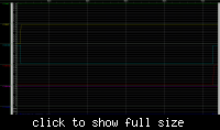
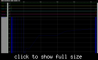
This is what the waveform looks like.
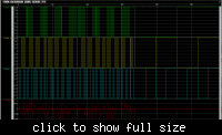

I use measurement statements to get the static current as Idd well clear of any input switching. I also use measurement statements to get the total current at each state transition by measuring 3/4 of a clock cycle prior to a transition to 3/4 of a clock cycle after a transition. Once I have all my measurements I calculate dynamic energy as total energy minus static energy.

Code:
Es = Vs * Is * T
Et = Vdd * Idd * T
Ed = Et - Es 
Pd = Ed / t

I must be doing something wrong, however. I've tried varying my clock cycle and I'm getting vastly different measurements for both dynamic and static power (as much as an order of magnitude in some cases). I've also seen ringing on Idd in some cases.

Is this setup correct? Do I have to use DC analysis to measure static power?

Any pointers or thoughts would be greatly appreciated.
 

You can measure static power by not clocking anything. In order to measure dynamic power you need to ensure that your maximum time step is short enough that the voltage & current transitions are show smoothly otherwise you will get errors. Then you need to measure average current - you should have some mathematical function that will calculate that from your output waveform.

Keith.
 
using .OP you can find the static power for every power supply used, and using .MEAS TRAN AVG you can find the time average of every power supply, to extract the exact value of dynamic power consumption you can subtract this the last value from the static one.
 
Ok, it seems the bulk of my troubles were from the late hour I was working. Over the weekend I managed to sort out the fluctuation in dynamic power I was seeing (I also started measuring power directly to cut the middle man).

Since I'm scripting the measurements I can't measure dynamic power only for the period where it's being pulled (I need to leave a big enough window to capture the power for the worst case transitions). As such, dividing out my clock period (measurement window) to find power was averaging that dynamic power across time periods where it was 0, pulling the number down. Instead I'm measuring dynamic switching energy now.

You can measure static power by not clocking anything.

I'm using the term clocking loosely here. I'm actually only changing my input vector so I can measure static power under all conditions. I am waiting 10 "clock cycles" after every transition before I measure static power. Here I measure static power for the pattern <1 1 0> as the average power from 692.5 ns to 702.5 ns (-1.9574e−09 W).


For dynamic energy I am measuring the average power at each state transition. Here I measure the average power for a transition from <0 0 0> to <1 1 0> from 915 ns to 925ns (-5.2243E-07 W).


ensure that your maximum time step is short enough that the voltage & current transitions are show smoothly otherwise you will get errors

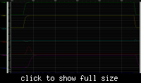
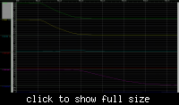
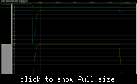
This is the resulting waveform from the <0 0 0> to <1 1 0> transition. My .tran statement is .tran 10n 1930n. Does this look OK?


I then calculate total energy for my dynamic measurement window.

Code:
Et = abs(-5.2243E-07) * 1E-09 = 5.2243E-15

Calculate static energy from the same window

Code:
Es = abs(-1.9574E-09) * 1E-09 = 1.9574e−17

Then subtract out static energy to find dynamic energy.

Code:
Ed = 5.2243E-15 - 1.9574e−17 = 5.204726e−15

For the most part when I vary my "clock" now I am getting consistent Ed measurements (with spread of 4% of so). Given I am seeing some movement I don't think I have an accurate measurement for Ps. I am also seeing some cases where Ed is negative. I'm not sure if that's due to a bad Et measurement or my Ps being off.

using .OP you can find the static power for every power supply used

How can I use this in my case? I looked through the report file and couldn't find any indication of static current.
 
It is difficult to make anything of your static power without you zooming in to the current waveform to see the shape of the curve. After a transition it can take quite a while for static power to stabilise. A DC analysis would remove time from the simulation so would be another option.

For dynamic power it is important to device the conditions under which you want to measure it. In particular you need to decide on a data/clock rate. Then you need to be careful to ensure that the time period you average over is sensible. For example, if you clock at 1MHz you could measure over 1.5us and 2.5us and you will get a different answer. You will get a different answer if you arrange there to be one or two transitions within the measuring period even if the measuring period is the same.

Your dynamic waveforms look fine in that they have good, smooth waveforms so the time step is not too large.

I am not convinced by the negative power from the supply on a negative transition. Something looks wrong there. You may be pumping current in through your input voltage source. It might be useful to see the circuit and simulation setup.

Keith.
 
Keith, thanks for the quick reply.

Here's the device setup that I'm using for simulation. I am attempting to characterize the full adder on Vsupply0.

vddinpar = vddpar = 1.8
using TSMC 0.18 Regular models

Code:
VsupplyBuff VDDBUFF 0 vddinpar
Vsupply0 VDD0 0 vddpar
Vsupply1 VDD1 0 vddpar

* output capacitance
CS0 S0proper 0 30f
CC0 C0proper 0 30f

* input drive buffers
XinvABar VDDBUFF inA inABuffBar INV
XinvBBar VDDBUFF inB inBBuffBar INV
XinvCBar VDDBUFF inCi inCiBuffBar INV
XinvA VDDBUFF inABuffBar inABuff INV
XinvB VDDBUFF inBBuffBar inBBuff INV
XinvC VDDBUFF inCiBuffBar inCiBuff INV

* adder circuit with inverter loading
Xfa0 VDD0 inAn inBn inCin S0 C0 FA_1
XinvSUM VDD1 S0 S0proper INV
XinvCAR VDD1 C0 C0proper INV

* inA noise injection
Engen0 inABuff inAn NOISE_inA 0 rms
Re0 inABuff inAn 1T
Rv0 NOISE_inA 0 1

* inB noise injection
Engen1 inBBuff inBn NOISE_inB 0 rms
Re1 inBBuff inBn 1T
Rv1 NOISE_inB 0 1

* inCi noise injection
Engen2 inCiBuff inCin NOISE_inCi 0 rms
Re2 inCiBuff inCin 1T
Rv2 NOISE_inCi 0 1

 .temp    25.0000
 .op
 *.save
 .print v(s0) v(c0)
 .option post

And the full adder and inverter circuit schematics.


It's probably worth noting that I intend to inject input noise (currently rms = 0) once the setup is working. I expect adding noise on my inputs will add some short circuit power to my "static" power so I'm guessing DC analysis won't work in that case.

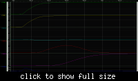
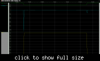
Here is the questionable transition with some zoom


---------- Post added at 16:29 ---------- Previous post was at 16:17 ----------

Forgot to zoom on the current line.

Here's the same <1 1 0> state with heavy zoom on the Vsupply0 current.


Based on this image, it looks to me like the dynamic draw hasn't settled yet.
 
I am a still puzzled by your current waveform, although you don't show your test stimulus which may be the problem.

Here is a simple example of what I would expect to see (for dynamic current). While there is a kick of current in each direction, the dominant current is in the same direction for each transition and these add together to produce the overall average (actually I meant to show mean not mean/cycle, but the conclusion is the same).

It might be worthwhile trying "gear" integration. With trapezoidal integration then there are often current "oscillations" at every time step which can cause problems.

Keith.
 

Attachments

  • Inverter power consumption.pdf
    16 KB · Views: 364
Keith, thanks for the inverter example. Based on your example I decided to back off to an inverter myself and try to match your results.

First, it looks like the capacitive loading (feedthrough current?) is having some effect on this high to low transition. I tried two runs here, one with 1f loading and one with the 30f loading I have been using.


At 1f loading I seem to match your waveforms fairly well (My setup seems to be measuring current flow opposite of the tool you used so I'm getting negative values). At 30f the discharge current overwhelms any switching current and they don't match so well (not sure if this was making it look like I was measuring current flow in the opposite, positive direction).

The choice of 30f was somewhat arbitrary, but I did want something to simulate output loading. The input capacitance of my cells is on the order of 1-5f.

Outside of the loading choice, I think I'm OK on the dynamic measurements. Correct me if I'm wrong here.

Also, I bumped the settle time for my static current up to 1k clock cycles. This is giving me a very stable current that is consistent across measurements. To double check I ran high and low DC
analysis on the inverter and my TRAN measurements match spot on.

I roughly think the setup is working now. I am, however, seeing some variation across simulation runs with the same input parameters. I tried repeating the same run multiple times and current is fluctuating by roughly 5%. Not too significant for low to high transitions were current draw is maxed, but I suspect this is overwhelming the high to low measurements were I see negative Ed occasionally. The deviation isn't really significant enough to worry about in terms of accuracy, but the fact that it's changing does make me concerned I'm missing something in my setup that is causing it.

Is there some source of randomness in the HSpice solution (transient sample points, etc.)? I'm not setting any initial conditions. Could this be the source of randomness?
 
Hmm. My loading was 100fFm and still didn't give significant current in the "wrong" direction. However, it would be worthwhile plotting the current from your input waveform source. That is effectively another power supply and won't be included in your power estimation. Ideally you will have some series resistance from the source waveform.

I am slightly concerned about the variability you mention. If you do the same run twice without changing anything you should get the same answer. I don't use Hspice but I am not aware of a hidden randomness being thrown in to the simulations. Any minor change will affect the results though, even though it might seem like it shouldn't, because time step positions can vary and if the maximum time step is not short enough it can have a significant effect around transitions.

Keith.


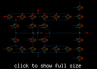
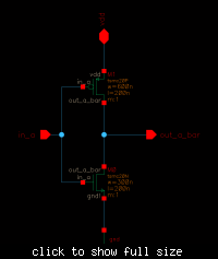
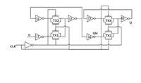
This is my circuit for which I want to calculate leakage and dynamic power.how to simulate this circuit & what should be the input values for calculation of leakage and dynamic power.
 

Status
Not open for further replies.

Part and Inventory Search

Welcome to EDABoard.com

Sponsor

Back
Top