Continue to Site

Welcome to EDAboard.com

Welcome to our site! EDAboard.com is an international Electronics Discussion Forum focused on EDA software, circuits, schematics, books, theory, papers, asic, pld, 8051, DSP, Network, RF, Analog Design, PCB, Service Manuals... and a whole lot more! To participate you need to register. Registration is free. Click here to register now.

purpose of one-shot block in PWM controller

Status
Not open for further replies.

allennlowaton

Full Member level 5
Full Member level 5
Joined
Oct 5, 2009
Messages
247
Helped
3
Reputation
6
Reaction score
3
Trophy points
1,298
Location
Taiwan
Activity points
3,081
good day EDA fellows...
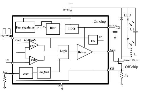
I got this PWM controller IC from a paper. From a figure below, there's a
one shot module after the oscillator. By the way, this oscillator utilizes a frequency spread technique. The oscillator produces a variable period with a fixed 50% duty cycle.
The paper said that the purpose of the one shot module is to rectify the duty cycle to a small value in order to avoid unexpected logic locking. I don't understand this statement. Please shed some light on this.

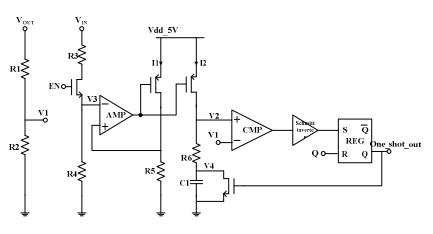
Below is the diagram of a one shot, I got from the other paper but the same author:
19_1284650304.jpg


Below is the diagram of the PWM controller IC:
48_1284650423.jpg
 

It seems that two pics had less relations.
In 1st pic., One-shot block used in constant on-time arichtecture buck controller.
In 2nd pic.,the function of one-shot module is to rectify the duty cycle to a small value as you mentioned before. For <50% duty cycle, one-shot is draw into the chip.If no, maybe erro action appear.
 
In my understanding, the one-shot's purpose is to prevent the output from switching multiple times per pwm period.
 
thank you edwintsu...


In my understanding, the one-shot's purpose is to prevent the output from switching multiple times per pwm period.
..

Can you expound it more please. I'm done with the oscillator, it produces a variable period(varied around its center freq.) but it has a fixed duty cycle. I'm confused with the purpose of the one shot.
 

thank you di*k_freebird....
yes, a ramp will be produced at the node V2, but I'm having problem regarding the EN, where it come from and is it a pulse?
any idea?
 

EN is likely your SDb (-Shutdown) signal, jamming it high gives
the timing ramp amp a reference above zero for the timing
current I1, replica current I2 ramps the timing node up, every
time it crosses the upper timing reference V1 the comparator
kicks the one-shot and resets the ramp.
 
is it right to assume that the EN signal is an external one? can I say that in this application (LED driver), it comes from dimming?
 

My understanding is opposite
May be right or wrong. I was referring to the well-known operation of industry standard current mode controllers. The logic functionality of the below controller hasn't been revealed in the discussion, so you have to guess about it. I expect it's more clear in the original paper. Usually, we have timing diagrams to clarify similar designs...
 
My understanding is opposite, its purpose is to prevent no switching per PWM period.
..This makes sense also because, I had seen the one shot from a paper that deals with Pulse Skip Modulation.
 

Can you share the paper, please?
 

Usually one-shot circuit used to set high-side switch on time.
In most case it is adjustable based on battery and output voltage.
 

Status
Not open for further replies.

Similar threads

Part and Inventory Search

Welcome to EDABoard.com

Sponsor

Back
Top