Continue to Site

Welcome to EDAboard.com

Welcome to our site! EDAboard.com is an international Electronics Discussion Forum focused on EDA software, circuits, schematics, books, theory, papers, asic, pld, 8051, DSP, Network, RF, Analog Design, PCB, Service Manuals... and a whole lot more! To participate you need to register. Registration is free. Click here to register now.

i need 12V DC to 220V AC inverter circuit

Status
Not open for further replies.
What i dont understand is that, a mosfet, for example can be used as a switch,

imagine a led in the drain connecting to supply, when (Vth >Vgs,) when gate voltage is applied about 10V lets say above the Source, the leds will come ON.

This is because current is flowing out of the drain powering up the LEDS.

But now imagine in a H-Bridge, where the Dc bus IS POWERING THE DRAIN !!!. of the high side. how does this enable the low side to generate an output between the source of high side and drain of low side.

Hope i make myself clear
 

KRYCHEK said:
But now imagine in a H-Bridge, where the Dc bus IS POWERING THE DRAIN !!!. of the high side. how does this enable the low side to generate an output between the source of high side and drain of low side?
When the high side Mosfet turns on and makes the output almost the same voltage as the +DC bus then the low side is turned off.
When the low side is turned on to make the output almost 0V then the high side Mosfet is turned off.
 

Thanks Audioguru.
That is the way it works.

Take a close look at this circuit. In fig.1a, the gates of Q1 and Q4 = High, say 10v.
While the gates of Q2 and Q3 = Low ( that is 0v).

In fig.1b, the sequence is reversed. this is done so fast, say at 50Hz.
You can see that, it is forbidden that Q1 and Q2 should come on at the same time.
This is also true for Q3 and Q4.

Cheers.
 

Why did you ZIP the simple picture of your schematic?
Simply attach the picture to your reply here.

Your high-side N-channel Mosfets are source followers. Then for the source to be at 340V the gate must be 350V, not 10V. The gate voltage must be 10V higher than the source voltage for a Mosfet to fully turn on.

"High-side Driver ICs" are made to convert a 0V to 10V input to a high voltage 10V swing for your application.

Your circuit must allow for a dead-time delay so that the turned-off Mosfets do not turn on while exising turned-on Mosfets are turning off.
 

Where did you get that from ?

Mosfets are not bipolar transistors. Every fet has gate voltage you cannot exceed else you punch a hole
between drain and source, and what you get is a latched fet that you cannot turn off.

Read manufacturer's data.
 

Fidelis Anyanti said:
Where did you get that from ?

Mosfets are not bipolar transistors. Every fet has gate voltage you cannot exceed else you punch a hole
between drain and source, and what you get is a latched fet that you cannot turn off.

Read manufacturer's data.
Are you talking to me?
I said that for the source to be at 340V then the gate must be 350V. Then there is only 10V between the gate and the source. The max allowed gate-source voltage is 20V.

The max allowed drain-source voltage for an IRF840 Mosfet is 500V.
 

I really hope you guys don't drop this thread. It has been very informative, I have read the entire thread, and am wandering if this circuit can be used to produce 240vac at 60hts for house use in the us. ie, 120 + 120 vac 180deg. what I mean is will it run an electric water heater?
thanks.
I am the new-by hear and don't really know anything about electronics.
thanks again every one.
 

Welcome 85mr2sc,

I have read the entire thread, and am wandering if this circuit can be used to produce 240vac at 60hts for house use in the us. ie, 120 + 120 vac 180deg. what I mean is will it run an electric water heater?
.


Water heater is a resistive load. with proper values and power handling, it will run an electric water heater with success.

Cheers.
 

Thanks for the reply Fidelis.
I understand about the water heater being resistive.
I should have seed the A/C unit and other devices that run on 220 vac.
Is their some way to build to inverters and run them simultaneously at 180 deg by way of some sort of time ic?
thanks.
 

Center taped transformer is a transformer with a refrence voltage at the mid point.:D
 

Re:i need circuit for full bridge inverter circuit

my project title is :mosfet driver for full bridge inverter...anyone can help me plz...
 

Hi denran,

Take a look At my post here :


Hope it helps you

cheers.
 

i need simple circuit for full bridge iverter using mosfet drivers...anyone can help???
 

pls give me a 12v to 220 schematic diagram of inverter without a transformer im very thankful to one who can provide me
 

To design an H-bridged inverter (12v to 220v ), you will need at least one high frequency transformer.

Good luck.
 

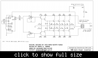
i build this inverter i used 10A step up transformer but the output is only mV i also checked my connection. can somebody help me to trouble shoot this circuit? these is very important for me to finish this project...

inverter circuit diagram


thank very much...
 
Hi,
I think the opamp drive circuit is faulty. Total feedback to - input this way, will starve the output transistors of current drive for greater output.

Cheers.
 

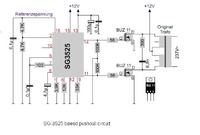
i have got a very very big iron core transformer. Can someone help me with schematics of a modified sine wave using sg3525 or sg3526. please note that i need modified sine nt sqaure or pure

---------- Post added at 16:08 ---------- Previous post was at 16:06 ----------

i have got a very very big iron core transformer. Can someone help me with schematics of a modified sine wave using sg3525 or sg3526. please note that i need modified sine nt sqaure or pure. my transformer is 10-10 primary and rated 1000VA
 

Here it is.

---------- Post added at 15:57 ---------- Previous post was at 15:53 ----------

Here it is.
 

Status
Not open for further replies.

Part and Inventory Search

Welcome to EDABoard.com

Sponsor

Back
Top