Continue to Site

Is Razavi's book wrong about this current mirror?

Status
Not open for further replies.

spur

Newbie level 3
Newbie level 3
Joined
May 26, 2010
Messages
3
Helped
0
Reputation
0
Reaction score
0
Trophy points
1,281
Location
Iran
Activity points
1,289

example 11.1 of Razavi's "Design of analog cmos integrated circuits" is about this current mirror.

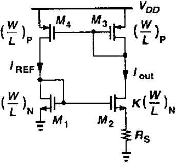
He estimates the change in Iout for a small change in supply voltage.
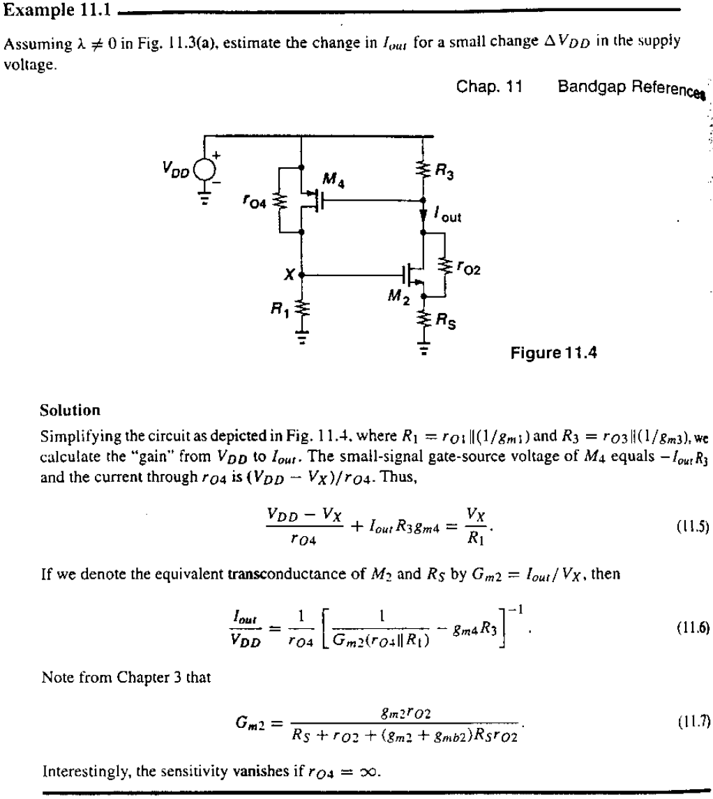
He uses an expression from Chapter 3 of that book to write \[G_{m2} = {{I_{out} } \over {V_X }}\]

The problem is, eq. 11.7 is derived for a case where drain of CS transistor is grounded; While in this current mirror drain of M2 is connected to a resistor (R3)

Is it correct to use equation 11.7 in this example?
 
Last edited by a moderator:

spur said:
The problem is, eq. 11.7 is derived for a case where drain of CS transistor is grounded
I wouldn't think so: Iout in Fig. 3.17 (p. 61) is a current source with (infinitely) high resistance. Otherwise the following equations (3.52 .. 3.55) wouldn't make sense.

spur said:
Is it correct to use equation 11.7 in this example?
Yes, I think so.
 

    spur

    Points: 2
    Helpful Answer Positive Rating
Hi.

spur, I think your doubts are reasonable and equation 11.7 is indeed incorrect (but it can be applied in this case). I'll try to show this using two-port equivalent model of the the common-source amplifier with source degeneration (attached figure).

Ro is output resistance (3.59), Gm is transconductance (3.55), Rdrain - resistor connected to the drain. Iout1 is output current with short-circuited output (Iout1 = Gm*Vx). Iout in the Figure 11.4 can be identified as Iout2. Using equation for current divider: Iout2 = Iout1*Ro/(Ro+Rdrain) = Gm*Vx*Ro/(Ro+Rdrain). Gm in the example 11.1 is defined as Iout/Vx (Iout2/Vx). Using previous equation we get Gm(11.7) = Gm(3.55)*Ro/(Ro+Rdrain). Thus when Rdrain has order of magnitude comparable with that of Ro equation 11.7 will give significant error. But in the example 11.1 Rdrain (R3) is resistance of diode-connected transistor (1/gm3) and in most cases Ro >> R3 = Rdrain, which means that Gm(11.7) = Gm(3.55).
 

    spur

    Points: 2
    Helpful Answer Positive Rating
i agree there's an error...but the problem is that razavi says that the sensitivity vanishes for ro4->infinity.

doing the small signal equivalent i had that the potential of the drain of M2 is simply (is it right?) Vdd-Iout*R3 (where R3 is the resistance of the diode connected M3). From this potential i calculated the sensitivity without any approximation:

Iout/vdd = (1+ gm2 r02*(R1||r04)/r04) / (r02 + Rs + R3 + r02 gm2 Rs - gm2 * r02 * R3 * gm4 *(R1||r04)/r04) )

and, even if ro4=infty, i have a non zero-sensitivity.

am i wrong?


ps R1 is the resistance of diode connected M1.
 

Status
Not open for further replies.

Similar threads

Part and Inventory Search

Welcome to EDABoard.com

Sponsor

Back
Top