Continue to Site

Welcome to EDAboard.com

Welcome to our site! EDAboard.com is an international Electronics Discussion Forum focused on EDA software, circuits, schematics, books, theory, papers, asic, pld, 8051, DSP, Network, RF, Analog Design, PCB, Service Manuals... and a whole lot more! To participate you need to register. Registration is free. Click here to register now.

Design of power distribution network for a PC expansion card

Status
Not open for further replies.

3Deye

Full Member level 2
Full Member level 2
Joined
Oct 7, 2009
Messages
125
Helped
3
Reputation
6
Reaction score
2
Trophy points
1,298
Location
EG
Activity points
2,159
Hi,

This is the first time for me to design a power network and I do not have suitable resources to start my design so I made this topic.

I want to design a power network for an expansion card that will be connected to a computer, its source of power will be from the PC power supply molex.

This molex provides +12VDC and +5VDC. My circuit requires different power values (0.75V, 1.2V, 2.5V and 3.0V).

The circuit includes an FPGA and will be implemented on 4-Layer (or more!) PCB.

Examples of power circuits that I am looking forward to design: (look at the power section of the PCB)
https://www.techpowerup.com/reviews/Powercolor/HD_5570/images/front.jpg
https://www.techpowerup.com/reviews/HIS/HD_5850_iCooler_V_Turbo/images/front.jpg
How can I design such networks?! Resources ?

If any more info is needed to make my question clear just let me know.

Thanks.
 

It is not clear what help you actually need. Do you need to know how to generate the multiple voltages from the +12V & +5V? If so, you should look at either buying DC-DC converters, or if you want to make your own, look at manufacturers web sites such as **broken link removed** and put your input/output requirements into their design tools.

Keith.
 

Re: Design of power distribution network for a PC expansion

Do you need to know how to generate the multiple voltages from the +12V & +5V?
Yes, that's exactly what I need to know + I need good resources to learn about the design of these circuits. I am a student and this is the first time to be involved in the design of such circuits.

I checked the link you posted and there are some design parameters that I am not familiar with! What's more efficient in my situation, to use DC-DC converters or to make my own ? I can't decide!

Plus, if I used DC-DC converters, is there any specific Manufacturer and design you would advise me to use ?

Thanks for your concern.
 

Buying a DC-DC converter is easiest. It is more expensive for the components than building your own, but if you only want one it isn't worth the effort of designing them yourself. If you are making them in production then you might need the lower cost.

I don't really know who are the "best" DC-DC converters. I have used TRACO ones in the past with not problems.

With the National link I gave, you should be able to specify the input & output parameters in the top right hand box and it will pick a suitable chip for you and do the design.

Keith.
 

Very well, the National link is very useful, I'll let you know my progress.

Thank you.
 

I need an DC-DC IC to convert from +12V to:

1. +2.5V @10A
2. +1.5V @10A
3. +3.0V @500mA
4. +0.75 @3A

I couldn't find the ICs that can do the job!
 

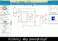
I think you must be doing something wrong. I put 12V to 2.5V/10A into the National tool and got 23 results. Picking one, the LM3150 gave me this design.


Traco don't do 10A at 2.5V that I noticed. They do 8A:


You may need to look for other DC-DC manufacturers if you want ready built ones.

Keith.

Added after 2 minutes:

These might work for 2.5V 10A


Keith
 

Hi all,
I think, that Fusion`s needed powers (1. +2.5V @10A/2. +1.5V @10A/3. +3.0V @500mA/4. +0.75 @3A) are typical FPGA values_I wouldnt search for some usual DC/DC converters, more for Linear Technology & Analog Devices Types!
For "Core powering" are their the best firms/vendors (in my opinion) and means too, that their are self to build...
You can check for solutions i.e. Xilinx`s homepage ->Spartan3 & 6 families, Evaulations Boards...
For me is very important, that your power is to sense at the load_most buyed converters dont have sens-in pins! :-(
Than, you need very clear layouting for these high currents, but relative low voltages on your PCB, and possibly multilayer!! (with an FPGA you must have so & so more as 4 layers...)
Otherwise you will have too much voltage drops between Converters & User/ICs & eventually so much problems/failures, that you can not wish it for your enemy...
K.
 

Re: Design of power distribution network for a PC expansion

@ Keith, thanks for your help, I saved those designs.

@ karesz, yes these voltages will be powering Spartan6 FPGA IO banks.
I understand from you post that the design of power network for an FPGA is sensitive and had many considerations to look at during the design + Simple DC-DC converter circuits will not be enough for clean power, correct ?
For me is very important, that your power is to sense at the load_most buyed converters dont have sens-in pins!
Sorry, I couldn't get this point, could you explain a bit more? or you can give me a resource to read more about it ?

Btw, I have the schematics of the SP605 board that is based on a Spartan 6 FPGA and I can see the power network design, but it's too complex for me so I am looking for a simpler design that will fit my needs.

SP605 Schematics:
https://www.xilinx.com/support/documentation/boards_and_kits/xtp067_sp605_schematics.pdf
You'll find the power components in pages: 21 to 26.

SP605 hardware user guide:
https://www.xilinx.com/support/documentation/boards_and_kits/ug526.pdf
Power architecture is discussed in pages: 52 and 53.
 

Hi,
only a short answer yet:
For me/in my opinion its important that the converter output voltage will be regulated with sensing on the load (on the FPGA)...
Maybe it exists some good converter on the market for these appl too, but I dont know it.
I like LT & ADI converters, but NI has the new LMVZ... family with good specs for these application too_I think.
I saw short time ago on some Spartan 6 circuit new ADI converters, they are very simple, and super practicable; all components(inductances too) are in the modules!! :)
I must search for that...
Regards
K.
 

I think the TRACO ones:
are remote sensing, as recommended by karesz, but take his advice and look at the one he suggested. While I have done high power DC-DC converters they have not been for CPLDs - they have been for things such as ultrasonic drives which haven't needed the precision & surge capability of a CPLD power supply.

Keith.
 

Hi Fusion,
I have it, it was from SA601 & is "LTM4616 - Dual 8A per Channel Low VIN DC/DC µModule", presents a 15x15x2.5mm, 144 BGA package. Delivers 2x 0.6...5V/8A(10Apeak)...
Other one was: National`s "LMZ1050x, LMZ1200x, and LMZ1420x SIMPLE SWITCHER Power Modules"
Specifications
* Integrated shielded inductor
* Supports 3.3V, 5V, 12V, 24V standard input rails
* Output voltages down to 0.8V
* Load currents up to 5A
* Enable, external soft-start, and tracking for sequencing
* Best-in-class thermal performance
* Low output voltage ripple
I saw yesterday an announcement from TI :), their nice modules can be your solution too: PTD08A010W
• Up to 10-A Output Current
• 4.75-V to 14-V Input Voltage
• Programmable Wide-Output Voltage (0.7 V to 3.6 V)
• Efficiencies up to 96%
K.
 

Re: Design of power distribution network for a PC expansion

Hello guys, thanks for cooperation :)
For me/in my opinion its important that the converter output voltage will be regulated with sensing on the load (on the FPGA)..
What do you mean by "Output voltage will be regulated with sensing on the load" ? What's meant by "sensing" here ?

LTM4616 - Dual 8A per Channel Low VIN DC/DC µModule
This module accepts a maximum of +5.5V input and the input in my circuit will be +12V. What's your point in choosing this module ? or you mean I should first use a 12V to 5V regulator then use this module ?

National`s "LMZ1050x, LMZ1200x, and LMZ1420x SIMPLE SWITCHER Power Modules"
These are suitable but the load current is 5A which I think is not enough!
Btw, How could I measure the maximum load current needed?

I saw yesterday an announcement from TI , their nice modules can be your solution too: PTD08A010W
Great ! these modules (the PTD08A010W) are used in the power network of the Spartan 6 SP605 board, you can find it in page 53 in this link:
https://www.xilinx.com/support/documentation/boards_and_kits/ug526.pdf
My question is, what's the function of the power controller UCD9240PFC ? can I use the PTD08A010W switching module alone or it must be used with the mentioned power controller ?

Another question if you please, What's the type of power network used in this card:
https://www.techpowerup.com/reviews/HIS/HD_5850_iCooler_V_Turbo/images/front.jpg
and what's the one used here:
https://www.techpowerup.com/reviews/ATI/Radeon_HD_5870/images/front.jpg

What's the classification of each ? and how do they compare to each other ?


Sorry for bothering you with my questions but I am still a beginner in this field :|
 

Hi,
1,
to first a speedy answer:
"What's meant by "sensing" here ? " = your FB-signal is = with your "sensing", these is to take from (or nearest of) the load (FPGA)...
2,
modern voltage converter ICs are limited to 5--7V input range!
Check pls. SA601 schema_it has a clear "POL (power of load) system" = to first it converts incoming power bus of 36-75V, or so, to 12 or even 5V(internal pwr bus) and its to change/convert every times in the naighborrow of Load to 3V3/2V5/1V2 or even 0V8 and so on...
Maybe you dont like it or means; "its too complicated", but these is the right way to distribute high current & low(est) voltage powers to the users/load.
Than is very important, that you must use professional (best) lowest ESR ceramics for decouplings, dielectricum minimumX5R-better X7R...
The converter vendors(appl. notes) of these converters tells/writes for you, which types are to use!
3,
LMZ10505 is a 5.5V input, 5A converter!!!
4,
LMZ1203 is a 12V input (but only) 3A converter...
I think you can search for some details of data sheets too!?
5,
Maybe that Spartan brings the same type (the PTD08A010W) too; I found it in a magazine: eetimes...
In all cases; I think their are the best components for your project!
6,
For rest of your questions I must study the datasheets_but sorry- I must go yet to sleep...
Gretings!
K.
 

Re: Design of power distribution network for a PC expansion

Hello K, thanks for the valuable tips.

I found those ICs and I think they're suitable: (need your opinion if you please)

For the FPGA: Renesas R2J20602NP or ST L6788A

For the Memory: ST PM6670S

?
 

Hi Fun!
Its a nice IC, but pls; I (personally) can not understand you :-( :
if the Spartan applications converter solutions are for you too complex, why do you select a another very complex solution for make that (theoretically) simpler!?
I should never select a way for some project that ca. 5x complexer is as possible other solutions, + needs more surface on board, has lot of discretes & through these worser reliability+ very critical layouting! :-(...
For me is PTD08A010W practically "the ideal solution" & LMZ1050x and LTM4616 are not bad for your project.
Apropos; if you have to design a PCI card; why dont select the +5V input voltage (instead +12V and all these converter problems) from the PC-Power bus?
For the DDR termination is these IC not bad, but (as befor) up to completing it for a right functioning voltage source; you will to do have some things_they are not every times light!
I would prefer some finished product (as practically every times, if its possible, than they are cheaper and needs less layout descriptions/problem solutings from me :)...
So a possible source is (Tracking Converter ): **broken link removed**, but they have lot of other & professional converter products too...
K.
 

Re: Design of power distribution network for a PC expansion

Hi,
For me is PTD08A010W practically "the ideal solution" & LMZ1050x and LTM4616 are not bad for your project.
Thanks for making things clearer, I understood your point about the ICs in my latest post and they're definitely not a clever choice for one looking for a simple solution, you're right!

For the PTD08A010W, the following is written in the datasheet:
"This module is a power conversion section of a digital power system which incorporates TI's UCD7230 MOSFET driver IC. The PTD08A010W must be used in conjunction with a digital power controller such as the UCD9240 or UCD9110 family"

Does that mean that this module can't be used separately ? by looking to the pin diagram:

mrr4ur.jpg


The description of pins:

dcdddu.jpg


It seems that it Send/Receive some signals to/from a digital controller ? do I need this digital controller or not ?

So a possible source is (Tracking Converter ): **broken link removed**
This one:
**broken link removed**

Is the simplest till now and meets our requirements, but I have a question similar to the above one, In the last page of the datasheet it says:
"Designed to accept its reference input from a G7NB-81A180. For use with other reference inputs, consult factory."
The G7NB-81A180 is found here:
**broken link removed**
Do I need to use the G7NB-81A180 chip ?!

Thanks.
 

Hi,
Yes, PTD08A010W needs a controller such as the UCD9240, but your ST solution needs a more complicated controller environment...
I dont see why should be the G7NB-81A180 the only one solution for the good source of 1.1--1.85V (or other ranges too) for DDR reference.
In my opinion you need max. similar programmable Termination Voltage Supply, w. similar output impedances & ripple/turn on time data.
Pls refer to that text (from first side top of G7NB-81A180`s datasheet: "These products may be used almost anywhere low voltage silicon is being employed and a nominal 12V source is available" :).
K.
P.S.:
Why do you not apply the +5V instead +12V of the PC-Pwr supply pls?

Added after 14 minutes:

If you dont accept a controller (but why not?) the proposed LTM4616:
..."is a dual-output standalone non isolated switching mode DC/DC power supply. It can provide two 8A outputs"...
Or even the LMZ10505 for max 5A loads (maybe two times to forseen, it needs not so much components...
By so "quasy discrete" regulators is the important question of "houskeeping" to decide!
I mean, your controller makes a listening the converted voltages too, so you can manage the power system.
If you miss a controller, must take another way, i.e. apply some extra ADCs, multiplexers or even other DAQs (DataAquisitionSystems):it can be to end more complex as a controller with DAQ onchip functions.
For me this all is to decide as a (important) system designer question...
Some time ago; we had a design with Spartan 3 & lot of individual & stand alone DC-DC Converters + ADCs & Mux`s = so a design is really complex/expensive (needs much components/ to populate it & have on stock/handlings; means all costs..), less reliable + needed ca. 40% of board surface! :-(

We can so much discuss over that subject, but I think an "integrated solution/ or modul" so far selectable/on the market is the best way to select.
So are (in my opinion) the SA601/605... evaluation boards good examples to follow...
K.
 

    3Deye

    Points: 2
    Helpful Answer Positive Rating
Re: Design of power distribution network for a PC expansion

Why do you not apply the +5V instead +12V of the PC-Pwr supply pls?
hmmm, I didn't think about it !

The PC molex connector have both 12V and 5V , Is there any shorts when using 5V instead of 12V ?
but I think an "integrated solution/ or modul" so far selectable/on the market is the best way to select.
So are (in my opinion) the SA601/605... evaluation boards good examples to follow...
I think that I'll use the same power design of the SP605 board.

Thanks a lot karesz, I'll let you know my progress :)
 

Status
Not open for further replies.

Similar threads

Part and Inventory Search

Welcome to EDABoard.com

Sponsor

Back
Top