Continue to Site

Welcome to EDAboard.com

Welcome to our site! EDAboard.com is an international Electronics Discussion Forum focused on EDA software, circuits, schematics, books, theory, papers, asic, pld, 8051, DSP, Network, RF, Analog Design, PCB, Service Manuals... and a whole lot more! To participate you need to register. Registration is free. Click here to register now.

non- contact current sensor baised on Rogowski coil

Status
Not open for further replies.
sorry bro
i couldn't get it

can you explain more to let me understand the situation

thnx for helping
 

for 100Hz low band limit reduce the 2.2uF to 22nF, & you need (as Brian estimated too) a speedier Amp too...
K.
 

i think i got it :D
thanx

so, thats mean i only can use high pass filter ??? for my period
 

for 100Hz low band limit reduce the 2.2uF to 22nF
The PI feedback adds a 2nd order high pass to the integrator characteristic. The capacitor sets the second high pass corner at
about 0.3 Hz, the first at about 1.4 Hz is set by the feedback gain. To get a suitable roll-off behaviour, both corner frequencies
have to be scaled. If you don't "see" the circuit behaviour at once, draw a bode
diagram or use a circuit simulator.

You'll get a low pass roll-off already by OP bandwidth and a second one by the coil self inductance. But you can add 1st or higher order
low-pass filtering after the integrator, if actually required.
 

To FvM

thanx for the more information

i just want to ask if i want to recalculate the values of the component to make is suit with my project

is it a normal equation for the gain ???

Added after 2 hours 15 minutes:

guys im having a question in my mind

why when i increase the frequency the output of the coil change , but if i connect the function generator to the oscilloscope it doesn't change
the voltage will remain the same , just just the frequency will increase
whyyy?

Added after 1 hours 37 minutes:

soooooo,,,,
the gain will be depend on what ???
 

why when i increase the frequency the output of the coil change
I wonder, if you actually succeeded in generating a frequency independant current in the 100 KHz and 1 MHz range. What's your setup?

If the test current is frequency independant, the amplifier must show integrator behaviour in the respective frequency range, to
achieve a "flat" sensor characteristic. And the rogowski coil's self resonance (due to stray capacitance) must be sufficiently separated
from measurement frequency.
 

first , i set the function generator to max amplitude which gives 23V Ac at the oscilloscope and start with 30k f and its sin-wave .

and this is my steps;-

1- i use the function generator to produce a frequency that pass through the coil
2- i measure the output of the coil by using an oscilloscope to see the wave form then see the V-peack value
3- i start it with 30K f, and its give me 22mV AC from the coil.
4- i increase it to 60K f , and its gave me 38mV AC from the coil.
5- increase it to 90k f , and its gave me 52mV AC from the coil.
and its going on
when i increase the frequency the wave will increase and also the V-peak value ...
 

i use the function generator to produce a frequency that pass through the coil
You don't clarify, how you generated a test current that's sensed by the coil. But the results seems reasonable anyway, because
they are basically corresponding to the fact, that a rogowski coil senses di/dt rather than i. So the coil output voltage can be
expected to increase with frequency at constant AC current. The integrator amplifier has to convert this output into a frequency
independant measurement.
 

    abadi250

    Points: 2
    Helpful Answer Positive Rating
Hi,
I think, for di/dt senses is a Square exciting better as sinus-or?
K.
 

    abadi250

    Points: 2
    Helpful Answer Positive Rating
i let the wire pass through a coil and connect its ends by the cable of the function generator

got it ??
or what ?
 

got it ??
So you are using the function generator (50 ohm impedance?) as a current source. Not actually obvious in my opinion,
but it's O.K., if you verified, that it can be operated this way. A high quality instrument with true 50 ohm output impedance
will give a frequency independant current, some simple instruments possibly won't.

I calculate from your data, that the rogowski coil has a rather high winding count (an about 200 mm n*coil area/circumference
geometry factor). This means, it has a considerable self inductance and is also sensitive to self resonance.

The V ~ f voltage characteristic is inherent to a dI/dt sensor, as said. Simply consider, that for
I(t) = sin (ωt)
you get
V(t) = a dI/dt = a ω cos(ωt)
a is the Rogowski coil sensitivity, a = µ0 * n * coil area/circumference
 

I mean square signal exciting instead sinus wave...
got it my fried_or what!?
K.
 

I mean square signal exciting instead sinus wave
That's possible. When operated with an integrator, the Rogowski coil reproduces the square wave. At the bandwidth limits, you get waveform distortions of course. For calibration of a Rogowski coil, I would prefer a sine current and a shunt resistor as a reference.
 

Sorry Frank, ich meinte natürlich den jungen heissbluter...
K.
Otherwise; tnx for infos_ I dont have experience with Rog.-coils...
 

did you get my bro, i have to explain more ?

Added after 5 hours 19 minutes:

hi bro
do you understand me ??
or i have to explain more !!!!
 

Hi ,
Is it a right decision to use differentail amplifier for the amplification of rogowski coil output (for reducing the common mode noises) ? Or is it must to use an ineverting amplifier ?
Please suggest me a good approach?

Thanks
Manju
 

Hi Friend

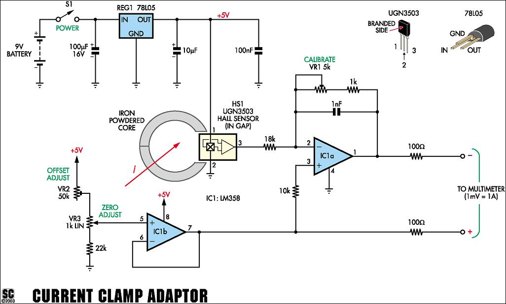
Best and better idea used hall effect sensor for good result and accuracy i attached here complete building instructions along with schematic

28_1269838322.jpg


regards
Fragrance
 

Is it a right decision to use differentail amplifier for the amplification of rogowski coil output (for reducing the common mode noises) ? Or is it must to use an ineverting amplifier ?
Most known circuits are feeding the Rogowski coild output directly to a non inverting integrator.
See a (manufacturers) literature overview:www.pemuk.com/publications.html
The basic advantage of this circuits is it's overload strength in case of transients with high dI/dt. Common mode interferences
can be supressed by electrostatic shielding and possibly common mode chokes.
Best and better idea used hall effect sensor for good result and accuracy
The sensors can't actually compete. A Rogowski coil is suited only for AC measurements but has outstanding performance
for high frequency and high current. Another domain of Rogowski coil are high precision/low-cost mains frequency AC current
measurements for energy meters and power quality instruments.

But in a wide range of precision, DC to high kHz current measurements, there's no alternative to compensating hall effect
transducers.

A direct measuring hall effect transducer (without compensation), as shown above, has limited linearity and a
considerable noise level. Also power bandwidth is an issue, full scale AC currents above e.g. 5 - 10 kHz are often exceeding the
core's power handling cabability.
 

Hali,
Maybe it will be useful for you/somebody:
K.
 

Status
Not open for further replies.

Part and Inventory Search

Welcome to EDABoard.com

Sponsor

Back
Top