Continue to Site

Welcome to EDAboard.com

Welcome to our site! EDAboard.com is an international Electronics Discussion Forum focused on EDA software, circuits, schematics, books, theory, papers, asic, pld, 8051, DSP, Network, RF, Analog Design, PCB, Service Manuals... and a whole lot more! To participate you need to register. Registration is free. Click here to register now.

Microcontroller power source

Status
Not open for further replies.

haneya

Newbie level 4
Newbie level 4
Joined
Jan 4, 2010
Messages
7
Helped
0
Reputation
0
Reaction score
0
Trophy points
1,281
Activity points
1,332
Hello, this is my first post here, I hope that it is on the right section.
I am working on a project based-on microcontroller, I completed the design on a simulation software(ISIS), its known that ISIS neglecting the voltage source, so I dont know how to provide the voltage supply to microcontroller (my power source is ATX PC power supply), I know that 5VDC should be connected to microcontroller through resistance the problem is that I don't know how to calculate the required resistance.

I will attach the schematic design for my project, I need some help with the required resistance.


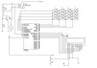
Am using PIC 16F877A
Power supply specifications: red 5v 20A, purple 5vsb 2A, yellow 12v 8A.

Thanks.
 

More than anything else, while connecting low-current circuits, such as yours, to high-current power supply, such as ATX, you need a protection circuit, not just A RESISTOR ..
An example of such a device is called PolyZen, see details here:
**broken link removed**

If you can’t get hands on that stuff you can consider a small-ohm, low-wattage resistor followed by 5.6V Zener diode ..
Resistor, for example 0.5ohm/0.5W, will act as a fuse and the Zener diode will protect your circuit against any overvoltage situation ..

Rgds,
IanP
 

Thanks IanP, I do have a regulator to provide a stable 5v an 1A, if thats what do you mea, but now is it ok to connect 5v (from regulator) directly to MCU ar it should be connected to a resistor ?


Thanks
 

The voltage regulator produces nice&clean +5V and that’s enough ..
Direct connection between the regulator and the microcontroller is all what’s required ..

Rgds,
IanP
 

    haneya

    Points: 2
    Helpful Answer Positive Rating
Hi,
Pls remember your regulators dissipation-they need good cooling!
With 1A & max 28V inp = 23W is to dissipate!:-(
ATX delivers 12V too >> then is your dissipated pwr. only ca. 30% from that_ ~7W:)

As I know PC-Power supplies/switchers needs in all case (pre)load resistor on +5V``:-((
If you dont have it; is danger is that will bourns out....

Other side:
I belief that some small AC-Adapter (for ex.a 5V/ 10W switcher, as for scanner, lap tops...) is the best supply solution for yourt application.
K.
 

Thanks guys for the replies, I have a question, Is it necessary to use capacitors on the regulators and between VDD,VSS ?
Another problem I want your help with, what if I want to use the purple line (5vsb 2.0A) should I add any extra components that is connected to Microcontroller ?


Thanks.

Anas
 

Hi haneya,
I would recommend:
by supplying external is every time a serial diode to design into (anode is to the external connector) a circuit, as false poling protection....
If you have only an external power adapter:
forget then 5V regulator, C2,C3 & put C1 (100 uF, but min 10-22uF) direct to uP, II with 100nF_C4.
If you have the internal 5V regulator to:
You should have all as is + the recommended serial diode in external 5V connection.
K.
 

@ betwixt , I did thanks.

@ karesz, can you please draw a how the connections will lock like?

I am now even more confused, because am forced to use the 5Vsb 2.0A (purple line), that means the regulator will not work (at least 8v required).

@ IanP
If you can’t get hands on that stuff you can consider a small-ohm, low-wattage resistor followed by 5.6V Zener diode ..
Resistor, for example 0.5ohm/0.5W, will act as a fuse and the Zener diode will protect your circuit against any overvoltage situation ..

can you show me a drawing that show the connection to micocontroller.


Am sorry if I ask for to much. Thanks
 

OK;
What version do you need pls?
K.
 

karesz said:
Hi haneya,
I would recommend:
by supplying external is every time a serial diode to design into (anode is to the external connector) a circuit, as false poling protection....
If you have only an external power adapter:
forget then 5V regulator, C2,C3 & put C1 (100 uF, but min 10-22uF) direct to uP, II with 100nF_C4.
If you have the internal 5V regulator to:
You should have all as is + the recommended serial diode in external 5V connection.
K.

This one :D
 

Also, the cicuit from IanP?
On it I see purple for Uinp upto max 28V!
& two times red; at pin 7& 20 by ATmega & at pin2 from 5V regulator.
What is 5Vsb 2A please?
Is it instead Vin max +28V to find?
K.
 

On it I see purple for Uinp upto max 28V!
& two times red; at pin 7& 20 by ATmega & at pin2 from 5V regulator.
No I didn't mean the purple line form IanP, I mean a purple wire that provides 5Vsb (stands for stand by voltage), it a wire that provide a 5V always, I mean even without running power supply.

Am using ATX PC power supply for my project.

Thanks.
 

Hli,
OK, yet did I understand what your purple wire is:)....
I belief, the scene is clear:
Your purple/+5Vsb put pls to the uP pins7&22 + C4 100nF, red signed as "from Vout +5V ", additional apply an10--100uF parallel with your C4_practically the existent C3.
Then you can eliminate C1 /C2 & the 7805V regulator_ this was what I wished to suggest for you, but my simple english:-(
K.
 

Thanks karesz, I guess this will work with me, am sorry I didn't understand you at the first post. when It comes to English then we are on the same boat :D
 

That is life!:)... Important is only: we wish understand us...
And dont forget pls: as I know, must PC pwr-supplies need a +5V load!!
YOu must search for that,I dont know what is the minimal load, but I do become 2 from my examplares dead, then I didnt applyd some (basic)load...
Good luck!
K.
 

    haneya

    Points: 2
    Helpful Answer Positive Rating
Status
Not open for further replies.

Part and Inventory Search

Welcome to EDABoard.com

Sponsor

Back
Top