powersys
Advanced Member level 1

Hello,
The matlab code is at below.
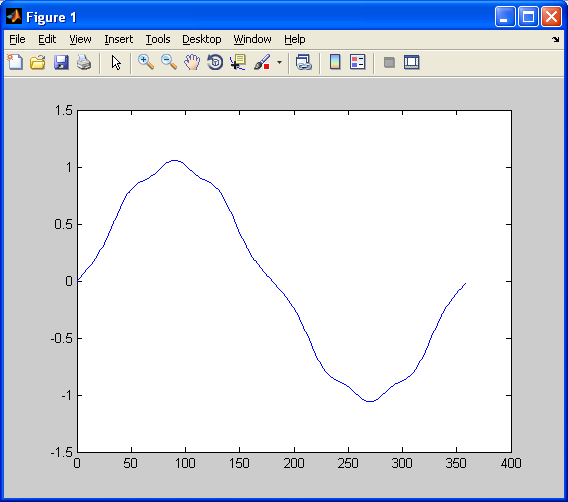
Kindly refer PART-A in the code. A signal, i.e. sigA, is constructed based on the given harmonic coefficients (i.e. h1, h3, ... h9).
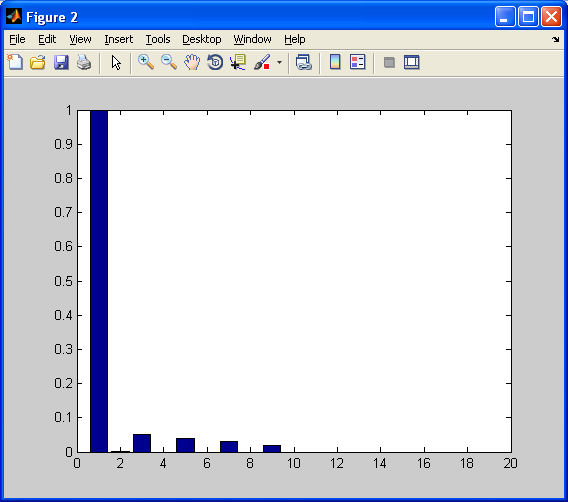
Then, in PART-B, Y=fft(sigA.y)/L is performed. A new set of harmonic coefficients is computed (the sign of the coefficients is determined by the polarity of angle(Y)) and saved as hc.
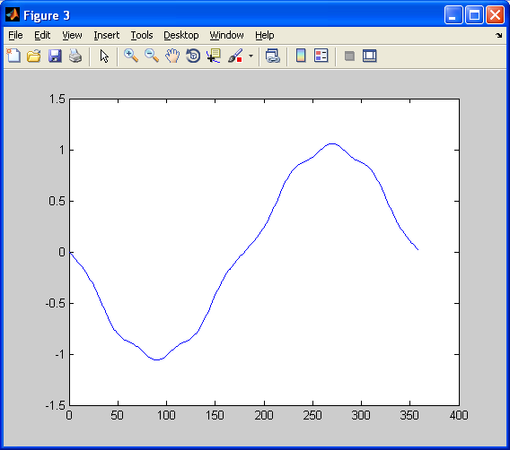
In PART-C, the signal is re-constructed based on the harmonic coefficients (i.e. hc) computed in PART-B. The signal is named as sigB.
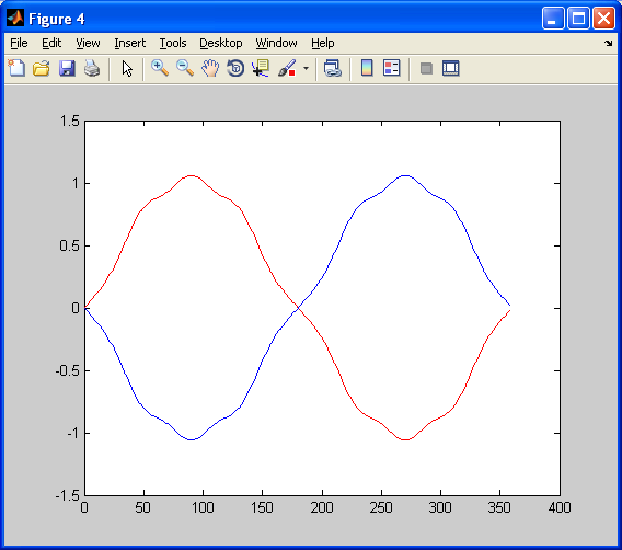
Kindly refer to fig4.png below. SigB is found to be inversion of SigA, i.e. out-of-phase with SigA. May I know why? Is the way I determine the sign of coefficient correct?
Figure(1)

Figure(2)

Figure(3)

Figure(4)

The matlab code is at below.
Kindly refer PART-A in the code. A signal, i.e. sigA, is constructed based on the given harmonic coefficients (i.e. h1, h3, ... h9).
Then, in PART-B, Y=fft(sigA.y)/L is performed. A new set of harmonic coefficients is computed (the sign of the coefficients is determined by the polarity of angle(Y)) and saved as hc.
In PART-C, the signal is re-constructed based on the harmonic coefficients (i.e. hc) computed in PART-B. The signal is named as sigB.
Kindly refer to fig4.png below. SigB is found to be inversion of SigA, i.e. out-of-phase with SigA. May I know why? Is the way I determine the sign of coefficient correct?
Code:
%%%%%%%%%%%%%%%
% CODE
%%%%%%%%%%%%%%%

clear all; close all; clc;

% #################################################
% PART-A
% Create Signal
% #################################################
% Coefficients for 1st, 3rd, 5th, 7th, and 9th harmonics
h1=+1.00;
h3=-0.05;
h5=-0.04;
h7=-0.03;
h9=+0.02;

step=1;

j=1;
for i=0:step:359
    tr=i*pi/180;
    sigA.x(j)=i;
    sigA.y(j)=h1*sin(tr)+h3*sin(3*tr)+h5*sin(5*tr)+h7*sin(7*tr)+h9*sin(9*tr);
    j=j+1;
end

figure(1);
plot(sigA.x,sigA.y);
% #################################################
% (END) PART-A
% #################################################


% #################################################
% PART-B
% Compute FFT of the signal created in PART-A.
% Retrieve coefficients for 1,3,5,7, and 9th harmonics again.
% #################################################
L=length(sigA.y)
Y=fft(sigA.y)/L;
magY=abs(Y);
angY=angle(Y);

figure(2);
bar(2*abs(Y(2:20)));
% bar(2*abs(Y(2:length(Y)/2+1)));

j=1;
for i=1:floor(L/2)
    hc(j)=angY(i+1)/(abs(angY(i+1))+1e-100)*magY(i+1)/magY(2);
    j=j+1;
end
% #################################################
% (END) PART-B
% #################################################


% #################################################
% PART-C
% Reconstruct the signal based on the harmonic coefficients
% obtained in PART-B.
% #################################################
j=1;
for i=0:step:359
    tr=i*pi/180;
    sigB.x(j)=i;
    sigB.y(j)=hc(1)*sin(tr)+...
                hc(3)*sin(3*tr)+...
                hc(5)*sin(5*tr)+...
                hc(7)*sin(7*tr)+...
                hc(9)*sin(9*tr);
    j=j+1;
end

figure(3);
plot(sigB.x,sigB.y);
% #################################################
% (END) PART-C
% #################################################


% #################################################
% PART-D
% Compare signals created in PART-A and PART-B.
% #################################################
figure(4);
plot(sigA.x,sigA.y,'r', sigB.x,sigB.y,'b');
% #################################################
% (END) PART-D
% #################################################
Figure(1)

Figure(2)

Figure(3)

Figure(4)

