Continue to Site

Welcome to EDAboard.com

Welcome to our site! EDAboard.com is an international Electronics Discussion Forum focused on EDA software, circuits, schematics, books, theory, papers, asic, pld, 8051, DSP, Network, RF, Analog Design, PCB, Service Manuals... and a whole lot more! To participate you need to register. Registration is free. Click here to register now.

How to do metal slot in Virtuoso, please?

Status
Not open for further replies.

gaom9

Full Member level 4
Full Member level 4
Joined
Oct 8, 2007
Messages
228
Helped
7
Reputation
14
Reaction score
5
Trophy points
1,298
Location
China
Activity points
3,294
skillcad

Hi,
I know when the metal is too wide, the metal "slot" must be placed for releasing stress of wide metal line.
In Virtuoso Layout Editing, how can I make it and how to add the slot to the wide metal, please?

Thank you!
Best regards!
 

metal slot

Hello.

Have a look at your process deisgn rules. That will tell you how to design slot areas in your wide metal.
 

metal layers used in virtuoso

Thank you for your reply.
Yes, I have read the rule.
But I don't know how to make it in Virtuoso.
I have some wide metal in Layout, but don't know how to add the slot on it.
What I want to know is how to implement the slot with the cadence Virtuoso tools.

Thank you!
Best regards!
 

virtuoso modify corner

the quickest way to make it is to draw a piece of metal to the limit of the design rule put a slot in it and use it as an array to quickly place down large areas. We have a script which slots our metal but I cant get my hands on it as its buried within teh kit. If I can I'll post it here.
 

cadence virtuoso cut

yeach, chop is a great way. select a metal, then ctrl + c.
 

chop metal slot

I only knew the command in making metal slit or 45 degree cut.

Its Edit>> Other>> Modify Corner
 

cutting slot in metal

In some process, there are some layers for metal slot. They are called metal slot. So we can use it to draw the slot.
 

metal slot rule

gaom9 said:
In some process, there are some layers for metal slot. They are called metal slot. So we can use it to draw the slot.

That's what we use with the AMS C35 process.
 

cut slot hole metal

search in your tech file. also go through the docs at austriamicrosystems web site.

hock
 

virtuoso metal slot script

You should not have to do this (although you should)!!
The Foundry will automatically insert metal slots according to their design rules.
If not, you need to go to a proper foundry.
TSMC, Chartered, Magnachip will all check your metal layouts and insert strtess relief cut outs as required.
This is no excuse for not following their design rules for metal line widths. If a designer claims he did not know then get rid of him..... Check it!!!

This is hugely important to the Fab guys --- get it right!
 

virtuoso slot script

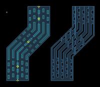
SKILLCAD offers a very handy tool to cut slot:
either create slot on a metal layer, or cut slot holes on metal.
at any angle paths, all slot shapes on grid, support stagger distance, and also can cut slot on corners....

Here is an example:


You can visit www.skillcad.com for more info
 

create slot metal

Slots are not as easy as one would think.
First of all you can create them by chopping out small metal areas to create a hole in wide metal.
You can also dra a rectangle or polygon in the "metal slot' layer - that will be later processed during mask creation process like ANDNOT - this way is significantly faster.
OR - you can use for example Calibre to create metal slots for you (see the documentation!!!).

The problem is that if for example you need to push 40mA through the metal line wide 40um. The rule requires to add slot for every 10um of metal(i.e. wide metal => 10um) then you need to add the area you cut out from metal to the total width of metal. i.e. if you add 3 parallel slots 2um wide, you need to add 6um to your bus to satisfy total width of metal bus. In my opinion those are one of the most annoying rules in IC design - although I know why those are there.
 
why use metal slotting

SKILLCAD SlotPath allows users to specify width by "gross width" "effective width" (actual valid width after slot), and "current". So the user does not need to worry about the current capability issue after slot.

And the slot can be created as a slot shape or holes directly on metal shape. The user can even save the slotPath as a pcell so that the user can change the slot size/space, path width/coordinates easily later on.

SKILLCAD also offers command to convert en existing wide path to slot path

See the attached SKILLCAD create slotPath command form. (visit www.skillcad.com for more info)
 
wide metal slots

I have only ever done it with the "cut" command but
that is a real nuisance after-the-fact so I generally
build busses with parallel maximum-no-cut stripes and
then cross-strap them every so often for balance. Once
merged the result is identical, it's just easier in sum.

Cute looking tool though.
 
Slot can be best done in Laker by a single click.
Select the required object & execute the command..... Thats it.
Rules will be taken care by itself.
 

did you realize this post is well over a year old?
 

One point that is important but is very often overlooked: slots should not impede the flow of the current.
Design rules do not quantify this. In general one needs to simulate the current flow in the metal traces, to get an idea of how the current is flowing and where current crowding is happening.

If wide metal trace is one-dimensional, it's obvious that the slots should be oriented along the direction of the current flow.
However, when the trace is bend (for example, at 45 degree or 90 degree), one should avoid placing slots in the areas of high current density (current crowding) - to avoid electromigration and local heating problems.
 
Status
Not open for further replies.

Part and Inventory Search

Welcome to EDABoard.com

Sponsor

Back
Top