elexlearner
Junior Member level 3

discrete balun
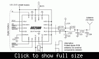
Can anybody help me in analysing the below circuit (mainly Balun design and adjacent filter). I couldn't able to understand how the values of these components were selected.
If I talk on Balun the formula says
√Rout*Rin/2*pi*f = L121 = L131
& 1/2*pi*f*√Rout*Rin = C122 = C132
But it doesn't matches to the real values mentioned in the datasheet of C2500 (BOM attached).
C2500 has Differential Load Impedance =80 + 74j = Rout (extracted from the datasheet)

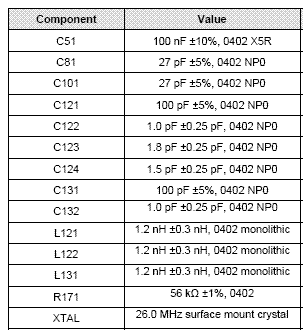
Component values are

[/img]
Thanks
Can anybody help me in analysing the below circuit (mainly Balun design and adjacent filter). I couldn't able to understand how the values of these components were selected.
If I talk on Balun the formula says
√Rout*Rin/2*pi*f = L121 = L131
& 1/2*pi*f*√Rout*Rin = C122 = C132
But it doesn't matches to the real values mentioned in the datasheet of C2500 (BOM attached).
C2500 has Differential Load Impedance =80 + 74j = Rout (extracted from the datasheet)

Component values are

[/img]
Thanks


