Fractional-N
Full Member level 1

edaboard
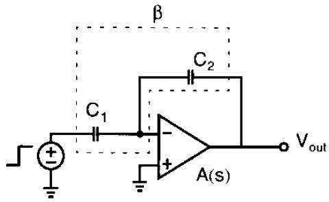
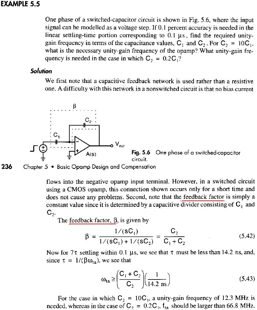
in the above circuit (one phase of a switched capacitor circuit). what is the feedback type? and what is the feedback factor?
i think the feedback type is voltage-current or shunt-shunt, and the feedback element is just the capacitor C2. but in johns&martin book it says otherwise :!:
in the above circuit (one phase of a switched capacitor circuit). what is the feedback type? and what is the feedback factor?
i think the feedback type is voltage-current or shunt-shunt, and the feedback element is just the capacitor C2. but in johns&martin book it says otherwise :!: