gaom9
Full Member level 4

Hi,
I am designing a VCO and using the switch capacitor to change the VCO output frequency range.
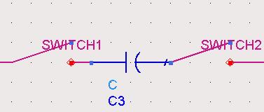
I have a question about the switch capacitor array. I have read some paper about the VCO design, and the circuit they used for switch capacitor is as Figure 1, which contain two capacitor and one switch, but why do they use the circuit as shown in Figure 2, which contain one capacitor and two switches?
As the circuit in Figure 1, the equal value of the capacitor is only a half of one capacitor, and it will cost twice layout area.
Is that because of the capacitor quality factor? As the MOS switch will introduce some resistance to the circuit, so we should decrease the number of switch?
Can anyone give me some advice about this, please?
What is the difference between the two circuit in Figure 1 and Figure 2?
Thank you!
Best regards!


