Continue to Site

Welcome to EDAboard.com

Welcome to our site! EDAboard.com is an international Electronics Discussion Forum focused on EDA software, circuits, schematics, books, theory, papers, asic, pld, 8051, DSP, Network, RF, Analog Design, PCB, Service Manuals... and a whole lot more! To participate you need to register. Registration is free. Click here to register now.

ask for help: a microstrip filter design (Hfss)

Status
Not open for further replies.

a&f_hfss

Newbie level 4
Newbie level 4
Joined
Jun 19, 2008
Messages
5
Helped
0
Reputation
0
Reaction score
0
Trophy points
1,281
Activity points
1,316
hfss + microstrip filter design

here is my filter working in 2GHz.

But i have a problem on it. I simulated it in HFSS with two same models, i found their resultes are different. in one, the two resonators can coupled as shown
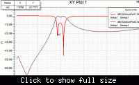
the other can not coupled.
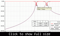
I realised it, the results more close with the uncoupled one.
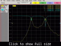

i am sure the radiation boundary (300/(1.5*4)) and solution frequency 2.0GHz are the same in this two models.

what is the problem? How can i obtain a 2GHz bandwidth as a bandpass filter with this structure?

Thanks everyone!
 

coupled resonators insertion loss ql q

It's easy. You only need to increase your input and output couplings and it will be all right.

Good luck!
 

reports on microstrip filter design

It looks like you have slightly over coupled resonators in the first case and two uncoupled resonators in the second. What you need to do is adjust the coupling and then check the input and output matching.

Best regards,
RF-OM
 

filter design hfss

Thanks RF-OM and Phytech.

But how can i increase the coupling? i had try to increase and decease the distance of the center slots. But in simulation, just this dimension it can couple.

One more question, is the real loss bigger, so this filter can not couple?
 

microstrip filter design

a&f_hfss said:
Thanks RF-OM and Phytech.

But how can i increase the coupling? i had try to increase and decease the distance of the center slots. But in simulation, just this dimension it can couple.

One more question, is the real loss bigger, so this filter can not couple?

The coupling you referred to is coupling between resonators, k12. In order to realized a filter, you need to couple your filter to outside world, namely, kin and kout, the input coupling and output coupling. What I was saying in my last post is that you need to increase kin and kout. Both your simulated curves showed the kin and kout are smaller than needed. On the other hand, you can reduce k12, then you will narrow your bandwidth.

The the loss is too big, the filter insertion loss will become big. But it has nothing to do with the coupling.

Hope this helps.
 

I mean to adjust both couplings internal and external. Internal or distance between rods will affect the bandwidth and overall filter shape. External will affect insertion loss and matching, these parameters are closely tight and always follow one another. If you have poor matching you have big ripple and insertion loss.

Best regards,

RF-OM
 

thanks a lots, Phytech and RF-OM. your explains are very useful.

But you talked about insertion loss, could you propose some method to reduce insertion loss? what i know is just to reduce the distance of the two side slots, but it didn't work well.

Thanks again.
 

Insertion loss depends primarily on two factors: required bandwidth and unloaded Q-factor of the resonators. You cannot change the bandwidth because it is spec number. Resonator Q-factor is what you may change, but there is some limitation in doablity and cost. You can evaluate insertion loss in dB as IL=4.34*Ql*SUM(gn)/Qu. Here Ql is loaded Q and defined by the bandwidth, Qu is unloaded Q of resonators and gn is filter coefficients. This is approximation, but usually this formula is good (about +/-0.5 dB).

Best regards,
RF-OM
 
Status
Not open for further replies.

Part and Inventory Search

Welcome to EDABoard.com

Sponsor

Back
Top