Follow along with the video below to see how to install our site as a web app on your home screen.
Note: This feature may not be available in some browsers.

hi,icsoul said:Nobody knows?


Alex_IC said:Taking into account first order effects only the transfer function is
v(outn)/v(inp)=Gm*Routn, v(outp)/v(inp=Gm*Routp, here Gm=(1+sRC)/R
n1cm0c said:A similar circuit is commonly used to remove the long tail in gaseous detectors for high energy particles. It's called a shaper there, or tail cancellation amplifier.
There's a description of such a circuit in here ,
http://dx.doi.org/10.1016/j.nima.2006.02.168
and the concept is explained here
**broken link removed**
a chip implementing this appears here,
**broken link removed**
look for the shaper section.
hope this helps.
hunk said:used to extend bandwidth of gm


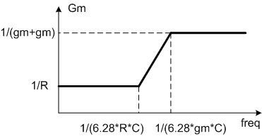
Alex_IC said:We can assume that gm>>1/(2*R), so that at low freq (where Cap is negligible) the effective transcondactance of the DiffAmp is Gm=1/R. At high freq the Cap shunts the R, and effective transcondactance is Gm=1/(gm+gm).

So more accurate eqation is
v(out)/v(inp)=(Rout/R)*[(1+RCs)/(1+gmCs)]


cdz said:This circuit is called amplify with high freauency boost.
Jim cage said:This circuit also has the advantage of degenration without an IR drop and having more headroom. The disadvantage is that it has higher noise due to current sources noises which are not common so the noise is uncorrelated at the Gm's output. The circuit is used to have broadband amplification where at high frequency the capacitive load dominates the output impedance and so the Gm will get higher to have the same gain.