Continue to Site

Welcome to EDAboard.com

Welcome to our site! EDAboard.com is an international Electronics Discussion Forum focused on EDA software, circuits, schematics, books, theory, papers, asic, pld, 8051, DSP, Network, RF, Analog Design, PCB, Service Manuals... and a whole lot more! To participate you need to register. Registration is free. Click here to register now.

Current Sensing using Opamp

Status
Not open for further replies.

nishal

Advanced Member level 4
Full Member level 1
Joined
May 4, 2007
Messages
108
Helped
10
Reputation
20
Reaction score
5
Trophy points
1,298
Activity points
1,936
current sensing with opamp

I need a schematic which senses AC Current (from IGBT) using a simple OPAMP and with gain adjustable. The output will be connected to PIC adc for displaying the load connected in the UPS.

Thanks in advance.

-Nishal
 

Do you also need a galvanic insulation between the measured current and the pic?
 

Thanks Heychel for your immediate reply

insulation is not necessary since current sensing output will be only in millivolts.

- Nishal
 

I think it can help you.

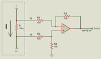
You should put a resistor (a smaller one, like 1 ohm) in serie whith the current source. Then, you should use a operational amplifier to measure de voltaje drop across the resistor.

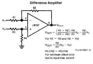
This circuit has a gain of 1 (1 mA on R results in 1 mV on Vo).


If you want another gain, here is the formula.

37_1195700347.jpg


Considerate that you'll have a sine signal, that cross between +v and -v.

You should use a rectifier bridge before R to have a all positive signal.

After the operational amplifier, you can use a filter to have a CC level, or take equally spaced samples on your PIC (>> 100Hz) to reproduce the signal value.

I hope that it helps you.

Excuse my English.
 

    nishal

    Points: 2
    Helpful Answer Positive Rating
Thanks Kepi for your detailed info

-Nishal
 

Status
Not open for further replies.

Part and Inventory Search

Welcome to EDABoard.com

Sponsor

Back
Top