Continue to Site

Welcome to EDAboard.com

Welcome to our site! EDAboard.com is an international Electronics Discussion Forum focused on EDA software, circuits, schematics, books, theory, papers, asic, pld, 8051, DSP, Network, RF, Analog Design, PCB, Service Manuals... and a whole lot more! To participate you need to register. Registration is free. Click here to register now.

Problem with demux 74ls138

Status
Not open for further replies.

jhanus

Member level 2
Member level 2
Joined
Feb 27, 2007
Messages
48
Helped
2
Reputation
4
Reaction score
2
Trophy points
1,288
Location
Croatia
Activity points
1,690
what is 74ls138

Hello,

I'm using demux 74ls138 with PIC16F84A, and I'm having big problems with it.

For settings:
ENABLE = 1..................|=>now 74ls138 is working in decoder mode
Both inverted ENABLE=0 |

for any adress exepct A2=0, A1=0, A0=0 I have correct values.

When I have logical 1 on expected output I see 4.10V which is good.
When I have logical 0 on expected output I see 1.41V which is also good.

But, when I set adress A2=0, A1=0, A0=0 on output Y0 I see this:

When I have logical 1 on Y0 I see 2.84V which is not good.
When I have logical 0 on Y0 I see 0.15V which is good, but diffrent from other output values.


First I thought that I burned the first one, so I bought another one, but this 74ls138 shows same behavior.
I tried first with no load, then with load(I=~14mA), same results.
So I'm doing something wrong, but what?!

Please help it's somehow urgent, thanks.
 

que es 74ls138(demux)

Your values seems not to be good. It looks like you missing a ground or vcc line.
The ic looks to work but very unstable because it takes the power from the inputs instead of vcc.
 

74ls138 port address

Values at adress 000 are terrible, when I have logical 1 I have 2.84V, and that is the biggest problem.

Vcc is connected to pin 16, and GND to pin8, so the problem isn't here.
 

demux 74ls138

I'm speaking from my own experience, please check your VCC and ground. Maybe a small pcb track error (a little resistance is also possible) or solder fault. Don't meassure over VCC and ground over the IC but from a (sure) ground to the VCC pin (5Volt) and from a (sure) 5volt to the ground pin.

4.1 volt and 1.1 volt out is not good. When nothing is connected to the outsuts or only 1 logic port the output voltages should be almost 5 volt and almost zero.

What is connected on the outputs?
 

    jhanus

    Points: 2
    Helpful Answer Positive Rating
use of 74ls138

"When I have logical 0 on expected output I see 1.41V which is also good."
No, 1.41V is not good.

Is the 74LS138 connected to other devices? Maybe they are causing the problem. Try disconnecting the other devices, and see if the 74LS138 now behaves normally.

If you are new to digital hardware, be sure you are counting the pin numbers correctly.

It sounds like you are measuring the signals with a voltmeter. If the signals have pulses, then a voltmeter can give you weird readings. Use an oscilloscope instead.
 

    jhanus

    Points: 2
    Helpful Answer Positive Rating
16f84a and 74ls138

I build and debug PCB all the time, and something like this happens with almost every board. There is no single answer to what it could be, but this is how I would go about checking.

Pre-testing, get a can of flux remover and a stiff brush(usually supplied), and give the PCD a good clean. This can often dislodge dirt/filings which are making connections, then check cicuit operation

1. Test voltage level on evey pin (not the track the pin is connected to, but the pin itself) Sometimes the pin is not properly attached to the track, pressing down with a probe sometimes makes a connection look good when it's not, be thorough!
2. test the resistance between every pin with a multimeter to find out if a couple are shorted.

Usually, by the time those to things have been done, the problem has presented itself. If not, then things become a bit annoying, you have to start looking for opens/shorts on the rest of your board.
 

    jhanus

    Points: 2
    Helpful Answer Positive Rating
74ls138

Yes plusminus, echo47, Old Nick you were right. (sorry for post lenght)

plusminus said:
4.1 volt and 1.1 volt out is not good. When nothing is connected to the outsuts or only 1 logic port the output voltages should be almost 5 volt and almost zero.

What is connected on the outputs?

I checked again only demux(decoder) and manualy changed all states.
I got this:

Vcc = 5.05V
I (all) = 17mA (7segment LED + 74ls138)
I (Yo) = 11.5mA same for other ports

Y0 0.15V(0.42V) - 3.99V(3.99V)
Y1 0.15V(0.42V) - 3.99V(3.99V)
Y2 0.15V(0.42V) - 3.99V(3.98V)
Y3 0.15V(0.41V) - 4.00V(3.99V)
Y4 0.15V(0.41V) - 4.00V(4.00V)
Y5 0.15V(0.40V) - 4.00V(4.00V)
Y6 0.15V(0.39V) - 3.99V(3.99V)
Y7 0.15V(0.42V) - 3.99V(3.99V)

Y0-Y7 are outputs, in brackets is voltage under load. Every output is connected to one cathode of LED display.


echo47 said:
Is the 74LS138 connected to other devices? Maybe they are causing the problem. Try disconnecting the other devices, and see if the 74LS138 now behaves normally.

It sounds like you are measuring the signals with a voltmeter. If the signals have pulses, then a voltmeter can give you weird readings. Use an oscilloscope instead.


74LS138 is connected to PIC 16F84A and it seems that there is the error.

RB0-A0
RB1-A1
RB2-A2
RB3-Enable inverted (data input)
RB4-Enable
RB5-nothing
RB6-nothing
RB7-nothing

I'm measuring with a voltmeter, but I slowed port change to every 3sec, so I can keep track.


Old Nick said:
Usually, by the time those to things have been done, the problem has presented itself. If not, then things become a bit annoying, you have to start looking for opens/shorts on the rest of your board.

I'm using breadboard, so it's easier.

I detected the problem, but what now, I have to use it with PIC16F84A!

Thanks!
 

74ls138 problem

Some strange suggestions:
- are the PIC port B registers all configured as outputs?
- try a little load (10K) at the outputs of the PIC. (output to GND)

- What do you meassure (voltages) at the outputs of the PIC?
 

All ports of PIC are configured as outputs, because I don't need any input for now.
One inverted enable is constantly on 0V, other inverted is trough PIC always on 0V, third non inverted enable is trough PIC always on 3.49V.


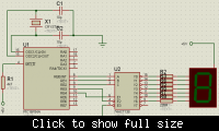
Here is how I connected it:


Voltages on PIC are:

If I have logical 1, on output I see 3.49V( it stays same with and without 74ls138)
If I have logical 0, on output I see 0.00V( it stays same with and without 74ls138)

PS
Now I know why I have 3.49V on outputof PIC, I'm constantly , every10us changing value of the port to 0V. Because I don't have oscilloscope I mesure it with voltmeter, so my mesured voltage is not accurate and I forgot that.
I will try to eliminate switching and post again.

Added after 3 hours 32 minutes:

Well now it's working fine, that is when I disable port switching, but my initial idea was to fast switch demux so that human eye can't see the switching of 7seg diodes.

What now? If I fast switch then I get again those side effects, is this normal?
 

Try it at a lower refresh rate. 10µs switching time is very fast. You need 50x7= 350 updates a second= ? 2ms. (50x = stable frequenty for the eye, 7 = 7 segment display.)

Other problem can be that it works but the leds are not visible. You need a much higher current per led segment. It's the total amount of energy per second you need for the led. Let us say: 10mA*1.6V*1sec =16mW. If you only switched 1/10 per second the energy to the led is only 1.6mW so the current can be higher -> 100mA.
Your solution can be to put a transistor driver between the led and the display + lower serial resistor.

Trying it at a lower speed should be the better solution. (for this amount of leds, if you have to drive a lot of leds your scanning frequency must be much higher thus alos the led current. )
 

    jhanus

    Points: 2
    Helpful Answer Positive Rating
Yes, you can pulse the LED fast. Many kilohertz is fine. Don't worry about the weird voltmeter readings. The meter simply displays the average voltage. An oscilloscope would confirm that the pulse amplitudes are fine. Try to find a scope! Many people and companies have old scopes that they would happily loan or donate to a student.
 

    jhanus

    Points: 2
    Helpful Answer Positive Rating
Thank you all for help, I managed to get it to work.

For now only one 7seg, in future 6x7seg.
I must admit that maybe somewhere I had a faulty connection, because I reconnected everything, tested bit by bit, then strobed and it worked.
This is also first time that I used external digital device, till now mux/demux/dec and many others were only theory.

plusminus, I will see what can I do about slower switching so LED's stay longer ON.
echo47,a scope would be great, but unfortunately here where I live they are not easy to get, and my budget can't afford it.

Let's hope that I won't have any more problems, bye.
 

Status
Not open for further replies.

Similar threads

Part and Inventory Search

Welcome to EDABoard.com

Sponsor

Back
Top