s_cihan_tek
Full Member level 2

hip4082
Hi all,
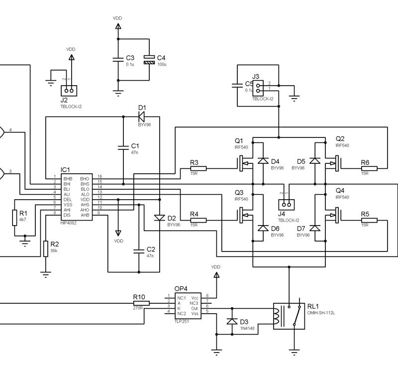
I'm using HIP4082 for a Full Bridge DC motor control circuit. I've constructed the simple inverter circuit which is given in the datasheet of the device and changed it's logic inputs to use the device for motor control. Gate connections of the 4 IRF540 MOSFET's are given below:
Top side of the H-bridge : T1 -> BHI; T2 -> AHI;
Bottom side of the H-bridge: T3 -> BLI; T4 -> ALI;
For motoring in one direction, the input signals I've applied to the HIP4082 are given below; These inputs should switch T1 and T4, while keeping T3 off. The reason for applying an inverse PWM to BLI is to charge the bootstrap capacitor which makes the MOSFET T1 conduct.
ALI -> PWM; BLI -> Inverse PWM; AHI -> logic low; BHI -> PWM;
According to the truth table which is given in the datasheet, these input signals should lead to these outputs at the gates of the MOSFETs:
T1 -> PWM ; T2 -> off; T3 -> inverse PWM; T4 -> PWM
While the outputs are exactly like this when the circuit is operating without o load, they change when the motor is connected. Even though I apply logic low to the input AHI, T2 goes to conduction mode as soon as the PWM signal goes to low and stops conducting before the PWM signal again goes to high. This leads to a decrease in the average output voltage level by applying a negative voltage to the motor. What is the reason of this behaviour? Am I applying wrong logic signals?
The pictures taken from the oscilloscope screen are given in the attached word document.
The switching freq is 15kHz, bootstrap capacitors are 47nF and values of the delay resistor and gate resistors are 36Kohm and 10ohm, respectively.
Hi all,
I'm using HIP4082 for a Full Bridge DC motor control circuit. I've constructed the simple inverter circuit which is given in the datasheet of the device and changed it's logic inputs to use the device for motor control. Gate connections of the 4 IRF540 MOSFET's are given below:
Top side of the H-bridge : T1 -> BHI; T2 -> AHI;
Bottom side of the H-bridge: T3 -> BLI; T4 -> ALI;
For motoring in one direction, the input signals I've applied to the HIP4082 are given below; These inputs should switch T1 and T4, while keeping T3 off. The reason for applying an inverse PWM to BLI is to charge the bootstrap capacitor which makes the MOSFET T1 conduct.
ALI -> PWM; BLI -> Inverse PWM; AHI -> logic low; BHI -> PWM;
According to the truth table which is given in the datasheet, these input signals should lead to these outputs at the gates of the MOSFETs:
T1 -> PWM ; T2 -> off; T3 -> inverse PWM; T4 -> PWM
While the outputs are exactly like this when the circuit is operating without o load, they change when the motor is connected. Even though I apply logic low to the input AHI, T2 goes to conduction mode as soon as the PWM signal goes to low and stops conducting before the PWM signal again goes to high. This leads to a decrease in the average output voltage level by applying a negative voltage to the motor. What is the reason of this behaviour? Am I applying wrong logic signals?
The pictures taken from the oscilloscope screen are given in the attached word document.
The switching freq is 15kHz, bootstrap capacitors are 47nF and values of the delay resistor and gate resistors are 36Kohm and 10ohm, respectively.